Subsections of Kit Information
2024 EFHW Transformer
Components
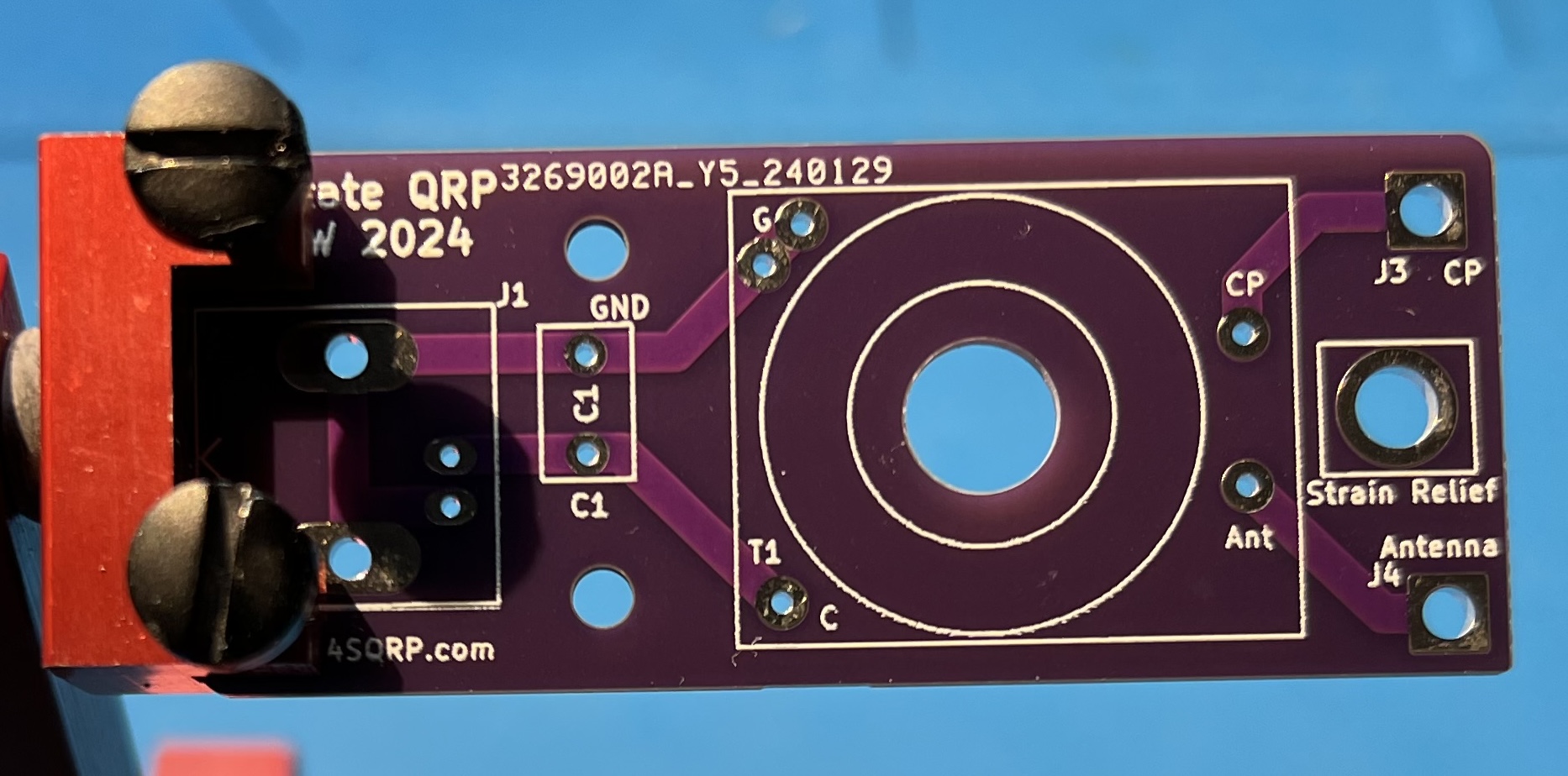
- 2024 EFHW Transformer board
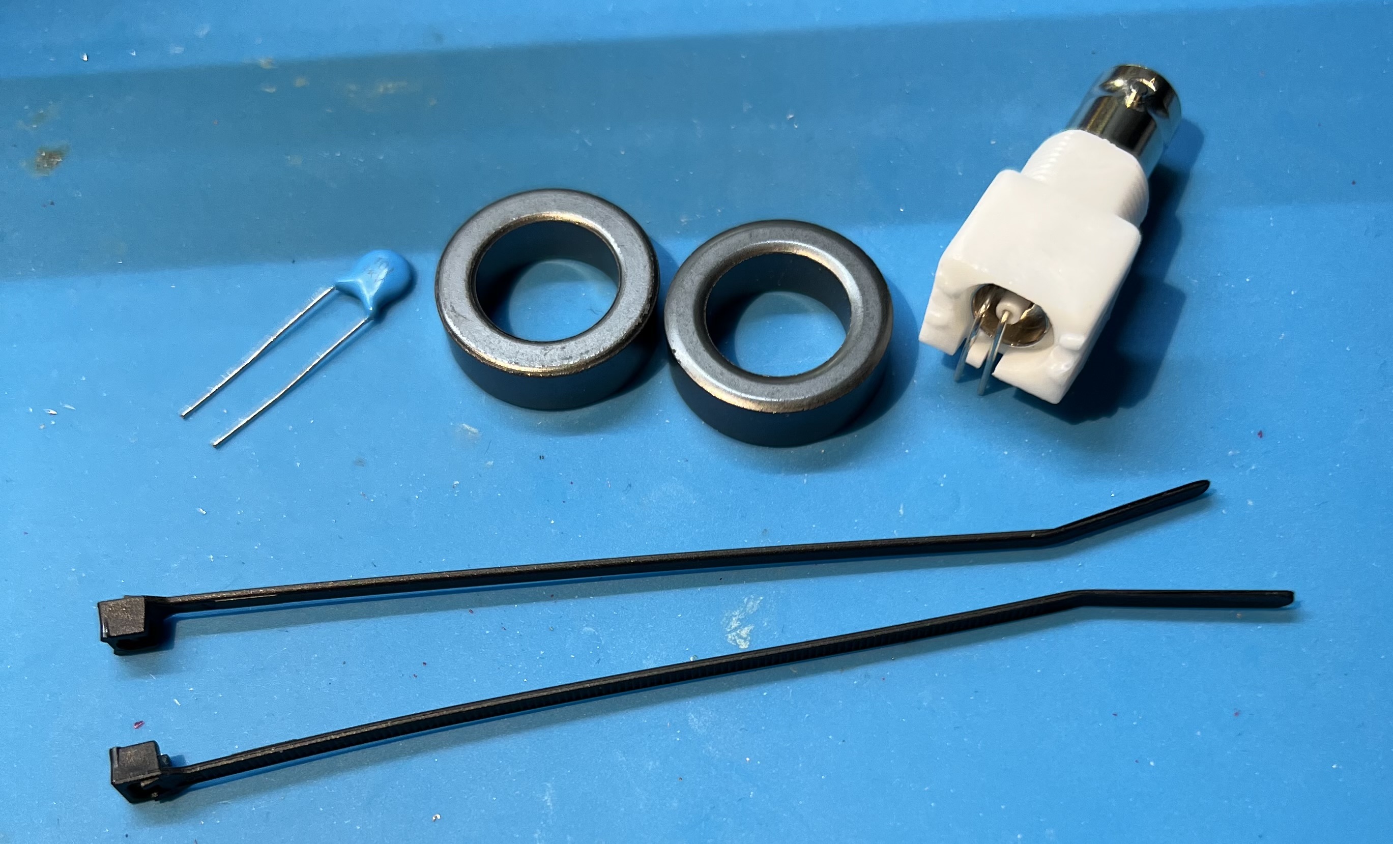
- 2 FT-84-43 toroids
- 44" of 22AWG enamel coated wire
- 1KV 100pF Capacitor
- 2 zip ties
Tools
- flush cutters
- mini pliers
- utility knife
- ruler
- soldering iron, set to 350C
- ceramic tip reverse tweezers (optional)
- spudger
- heat safe work surface (or board holder)
Instructions
Resist the urge to follow the convention of installing small components first!
By delaying the placement of the capacitor we’ll be able to do some test checks and give ourselves some more room to work.
Subsections of 2024 EFHW Transformer
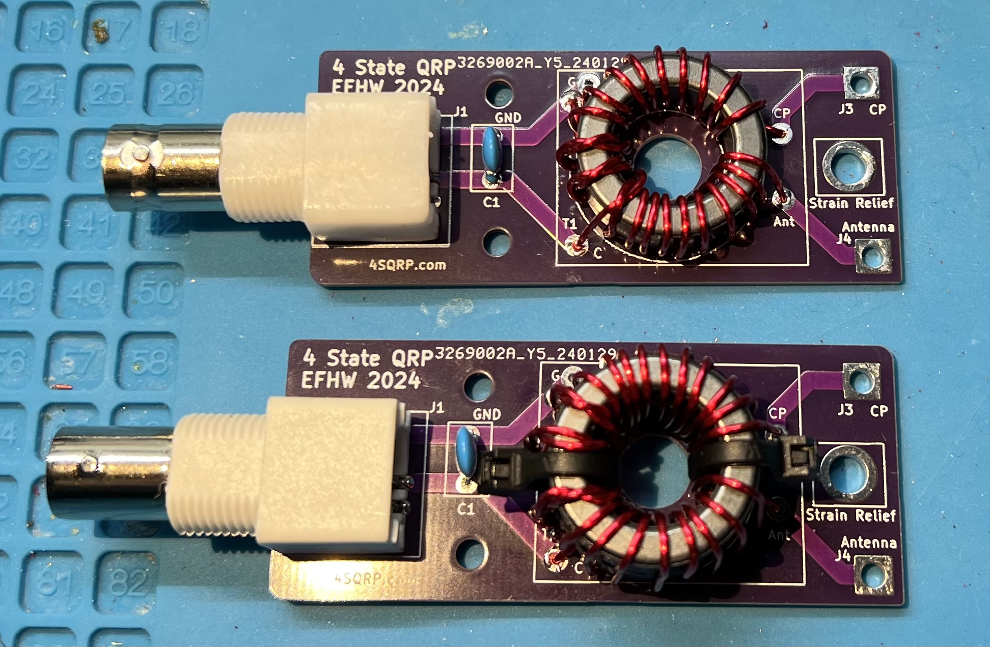
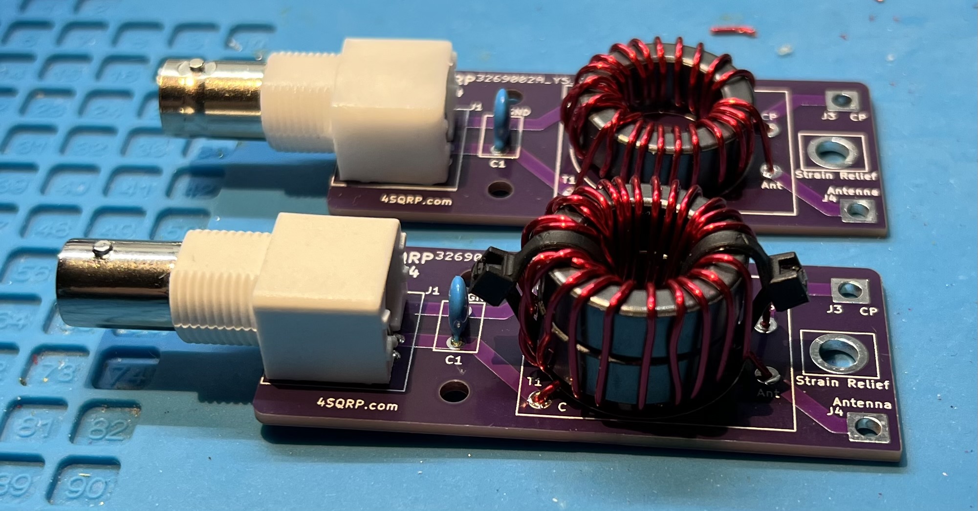
Double Stack
Winding
Use 20awg enamel coated wire. Primary uses 8" of wire, secondary uses 35" of wire.
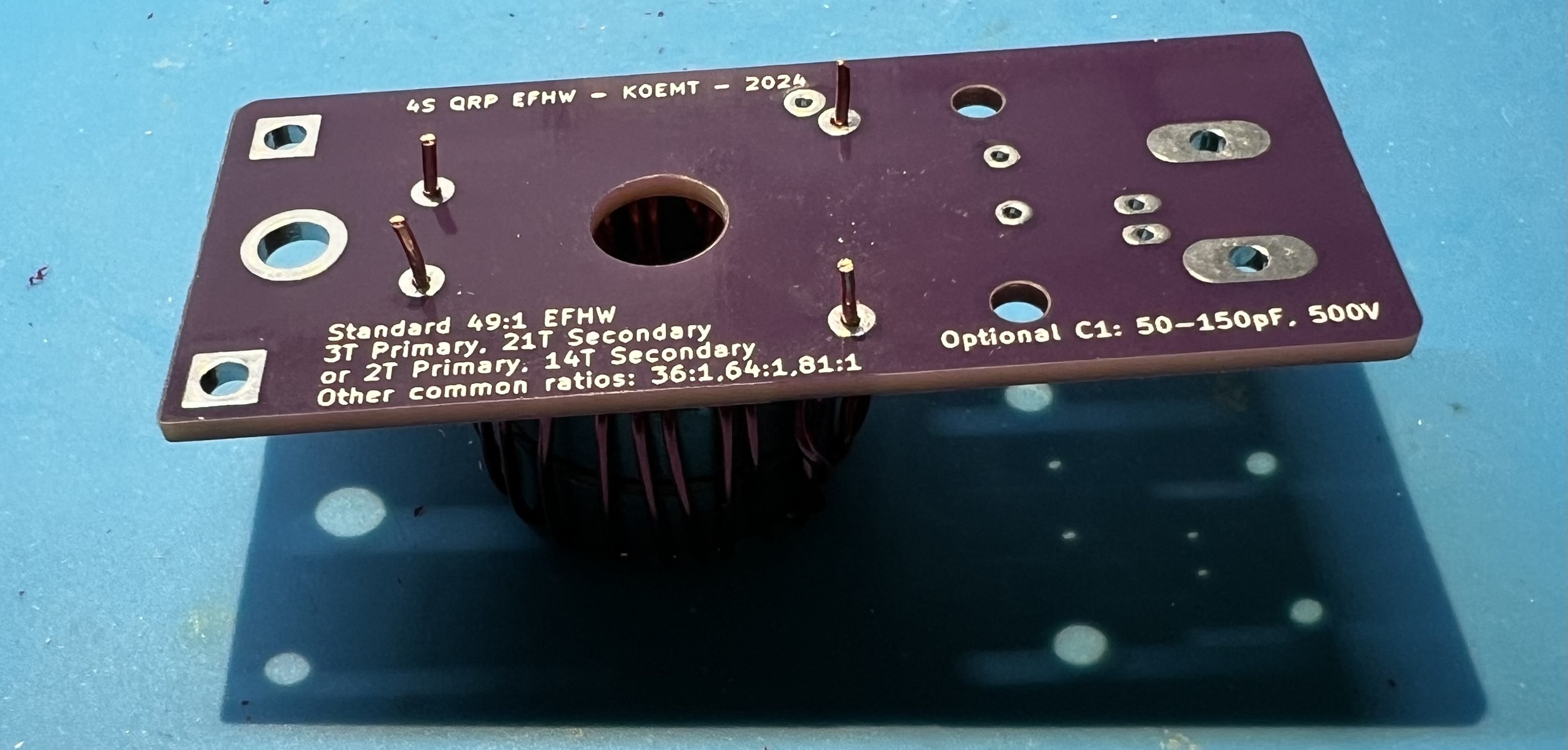
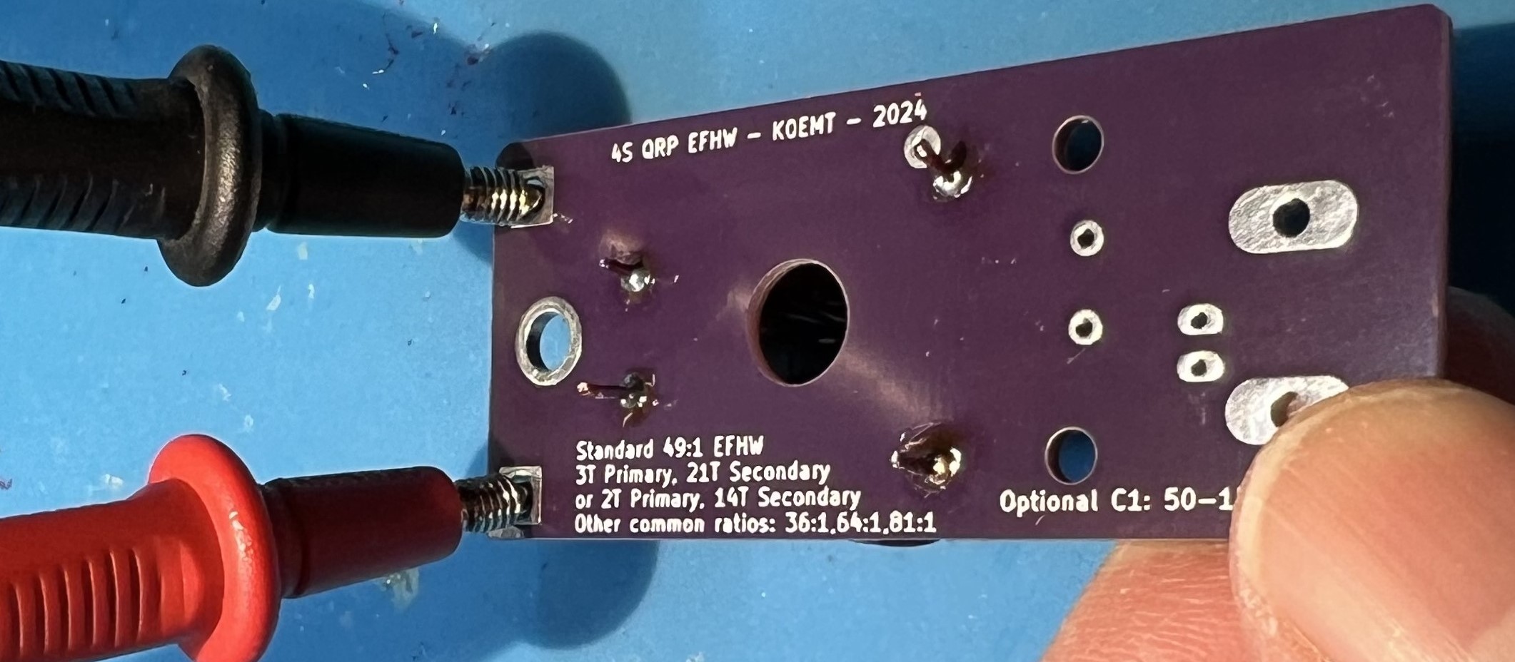
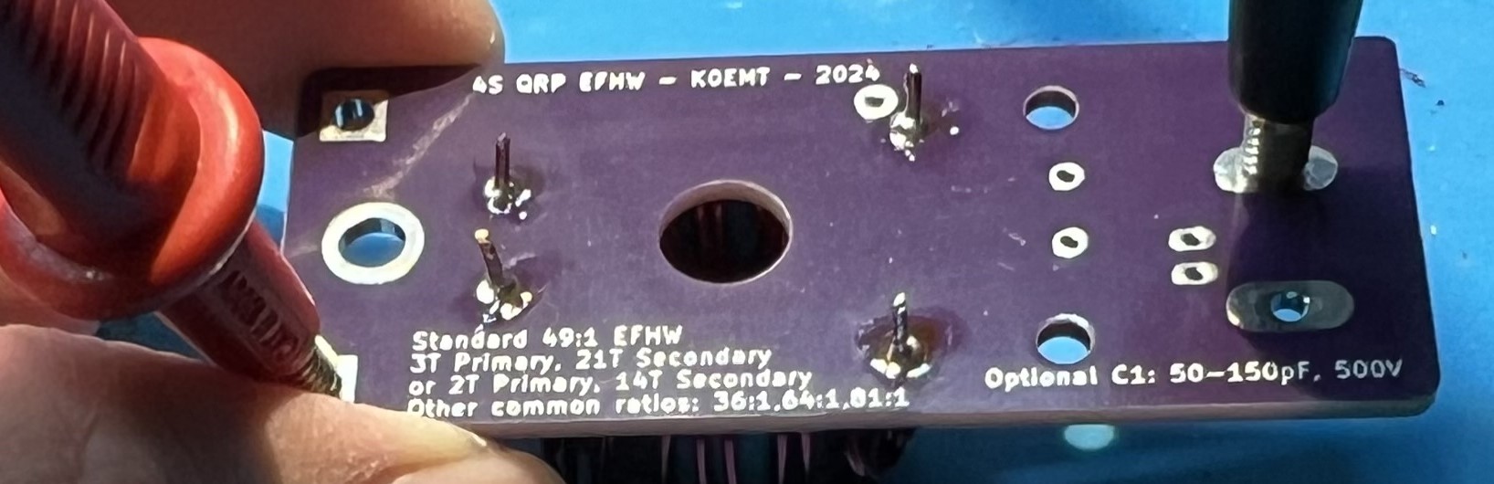
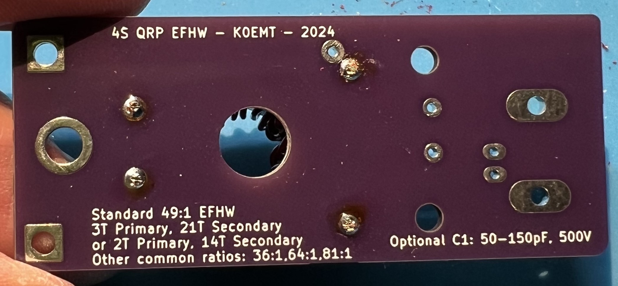
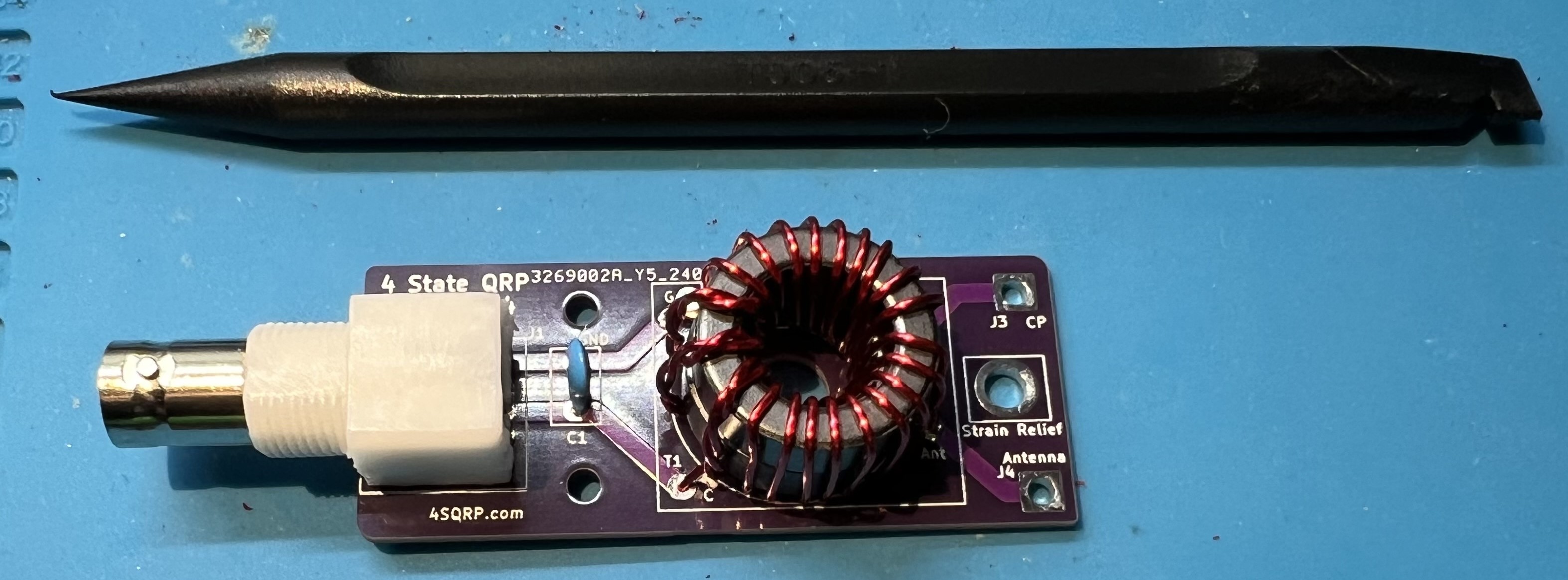
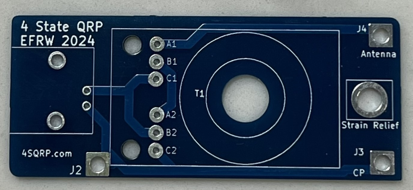
The bare board.
The capacitor, FT82-43 toroids, zip ties, and female BNC.
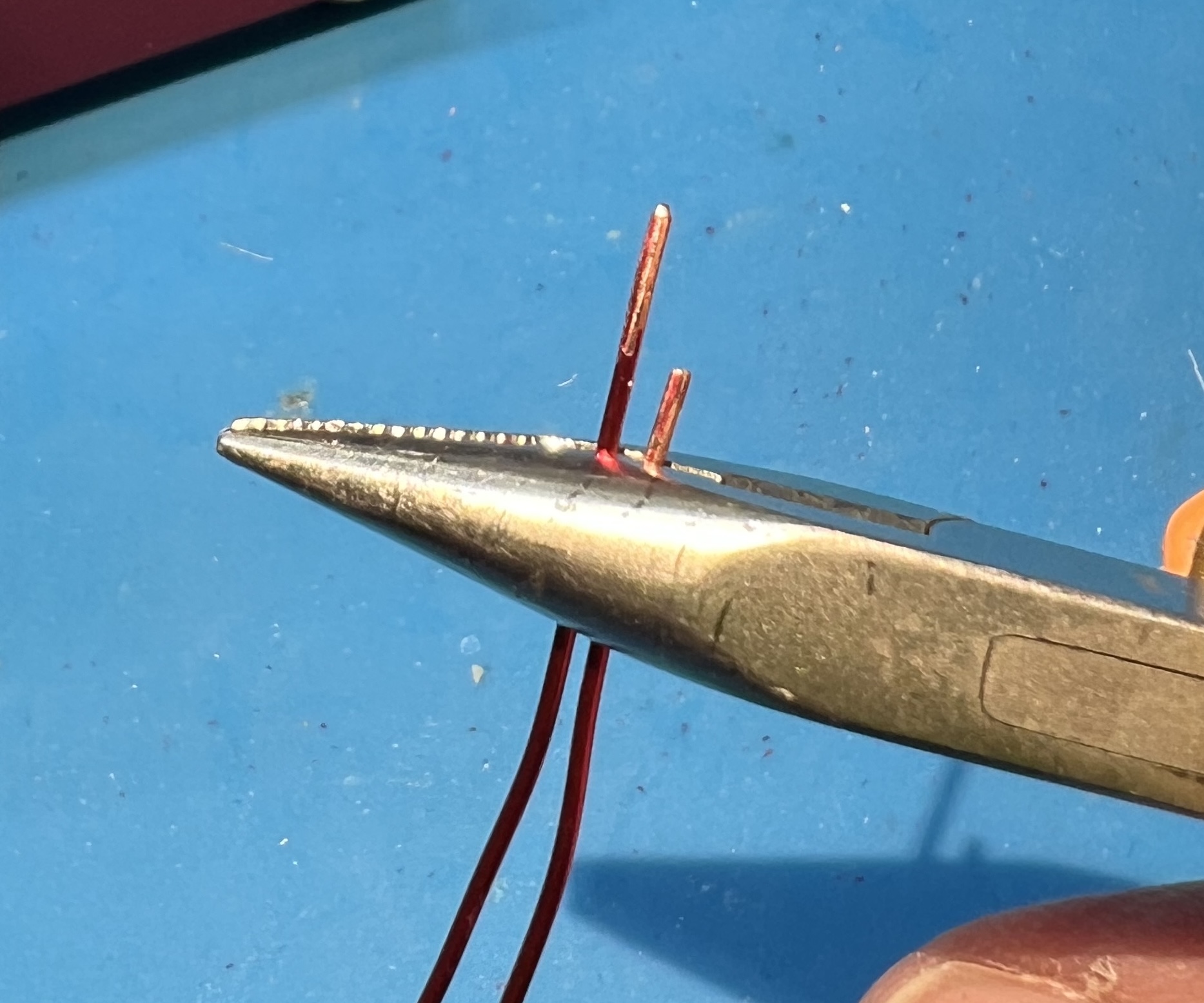
Cut your 8" wire from your length of wire.
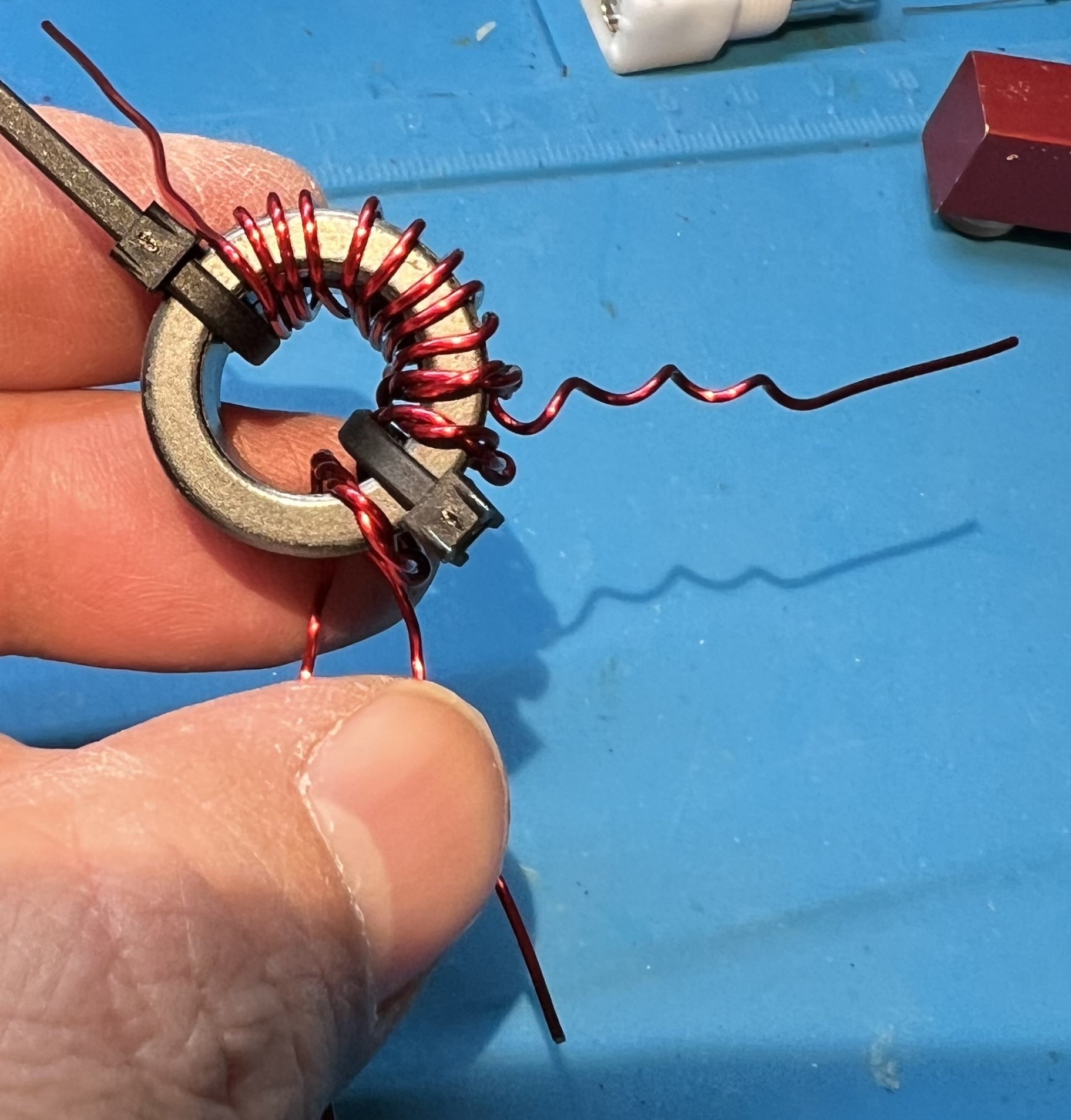
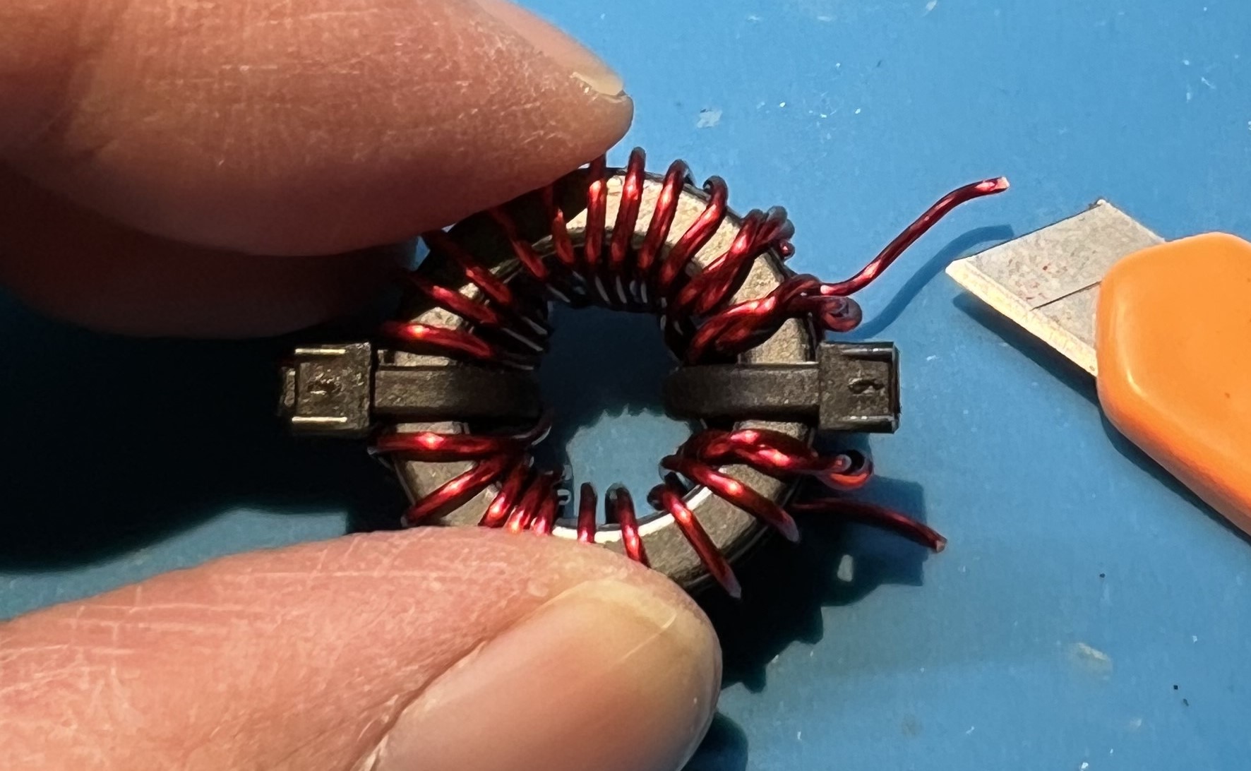
Fold them both in half to find the middle of each wire.
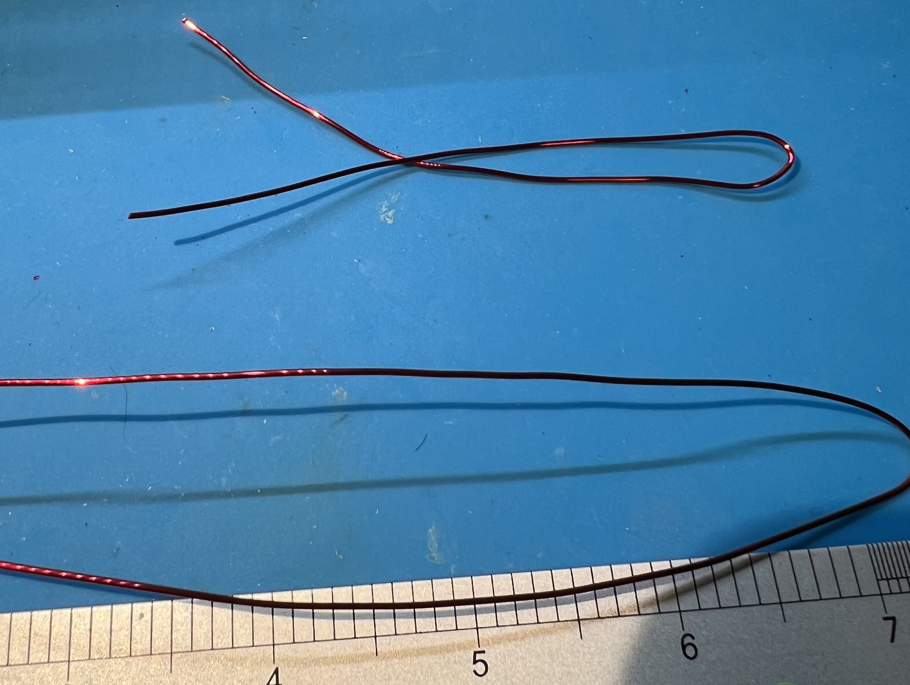
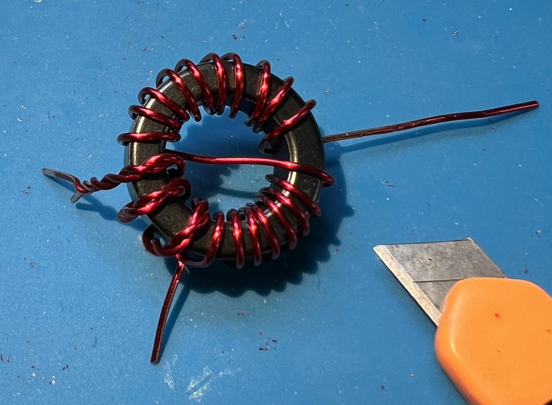
Grip the wire in the middle and twist some in each direction.
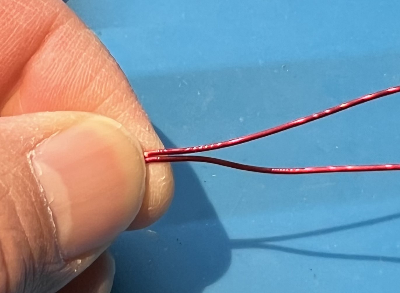
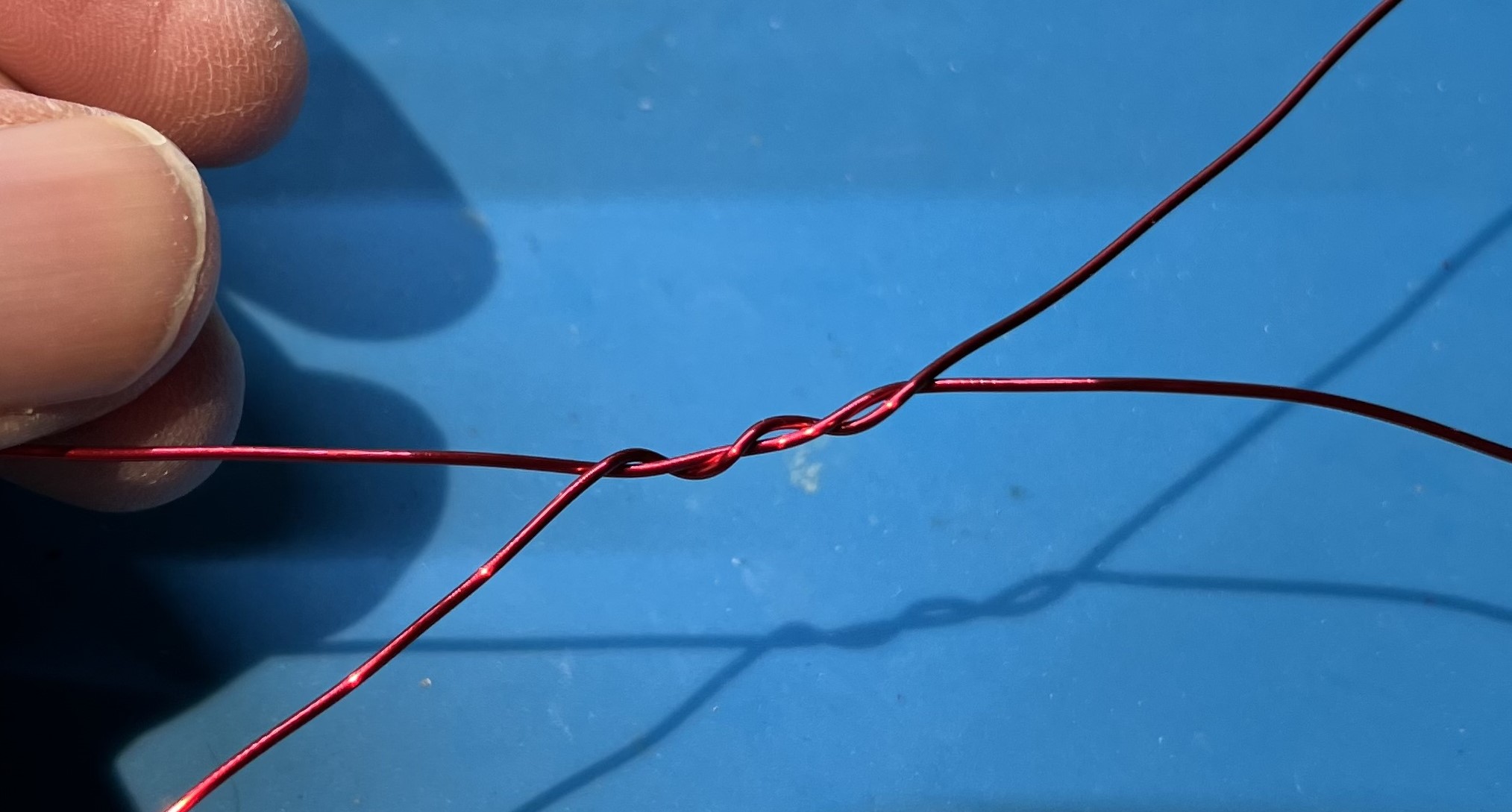
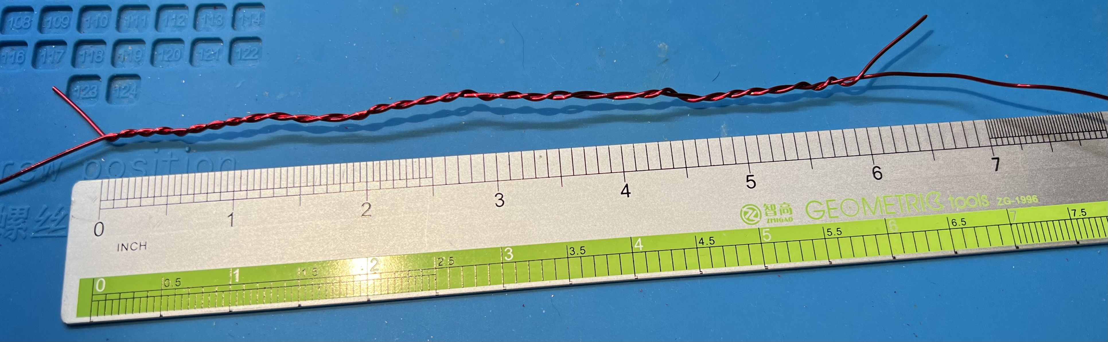
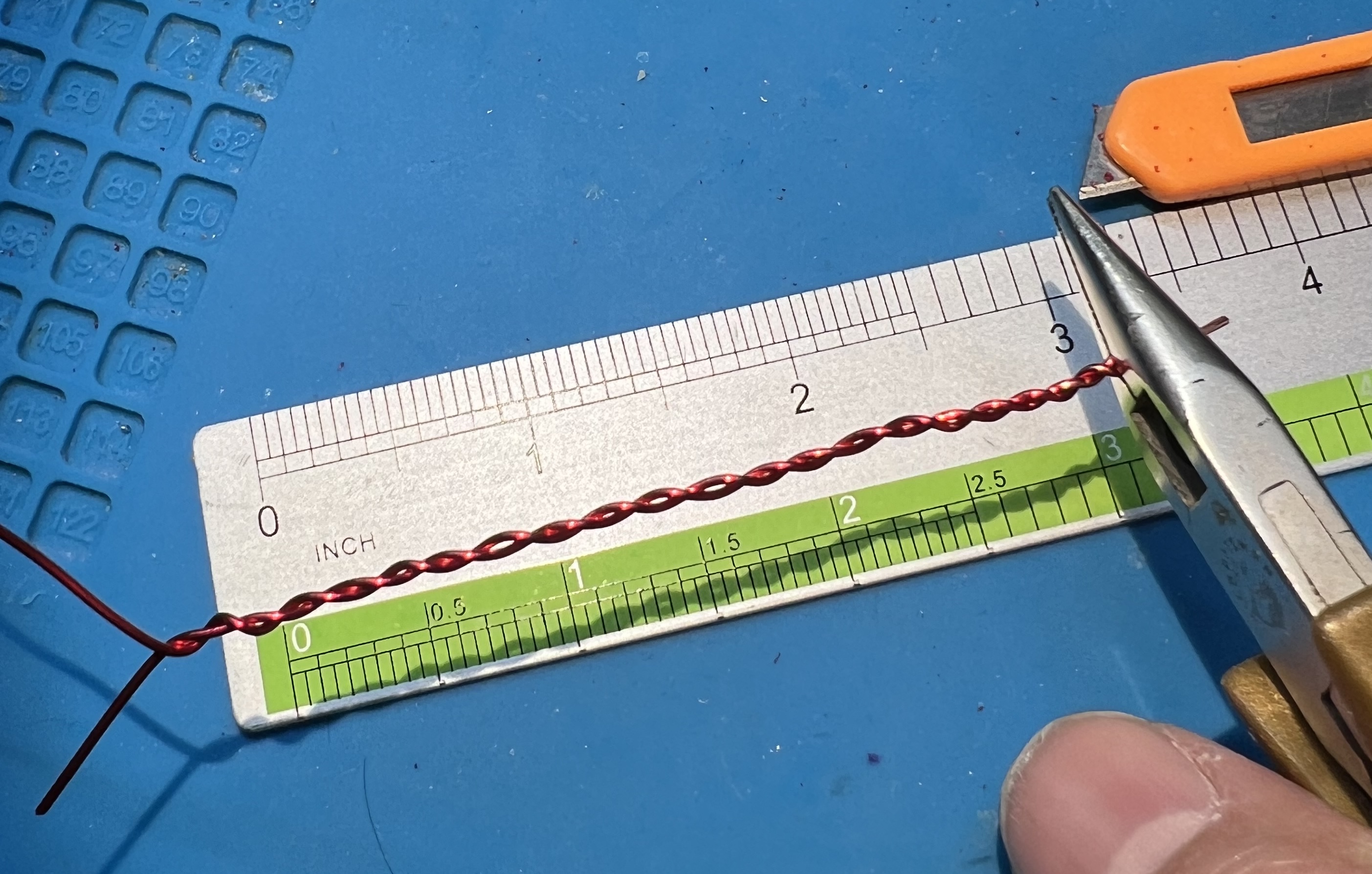
You need about 6" of twisted wire.
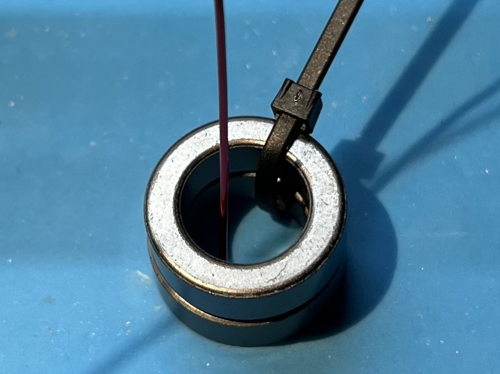
Use one of the zip ties to hold the double stacked toroids together.
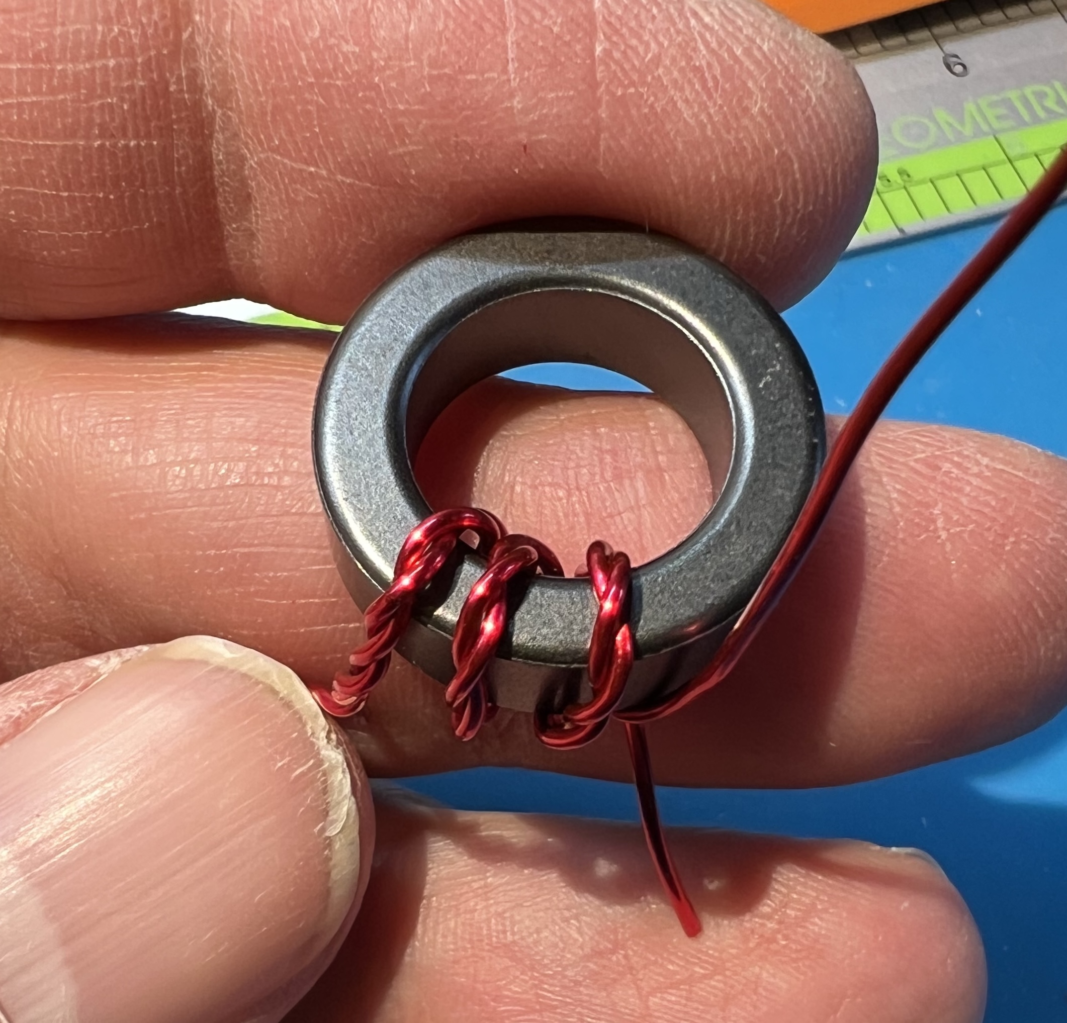
Insert an end of the wire through from the top.
Place the first turn of the twisted wire on the toroid.
This should be in the middle of the twisted section.
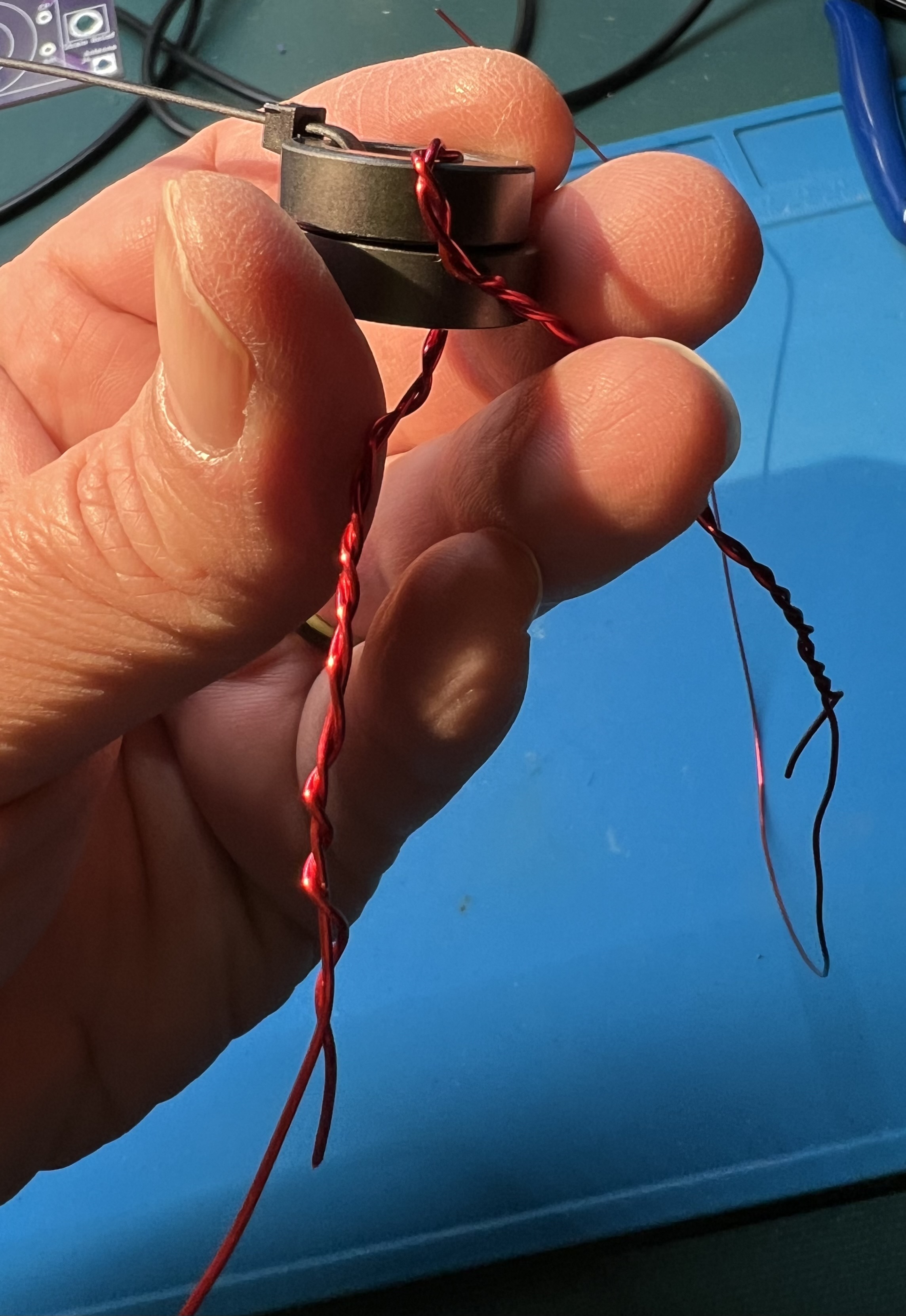
Use the second zip tie to secure the first (middle) turn of the twisted wire on the toroid.
Wrap an additional turn with both wires to the left (clockwise).
Wrap an additional turn with both wires to the right (counter-clockwise).
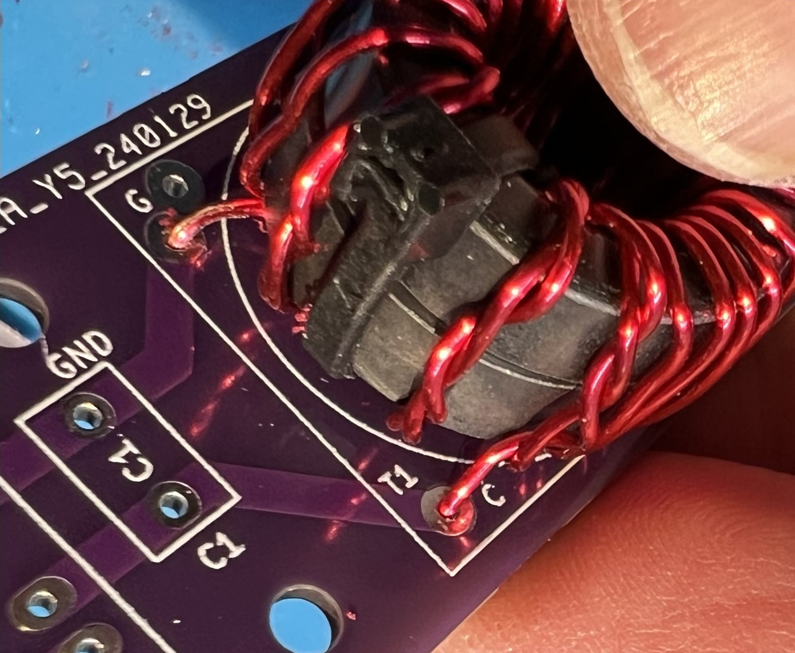
Check the twisted section against the location of the holes for the primary.
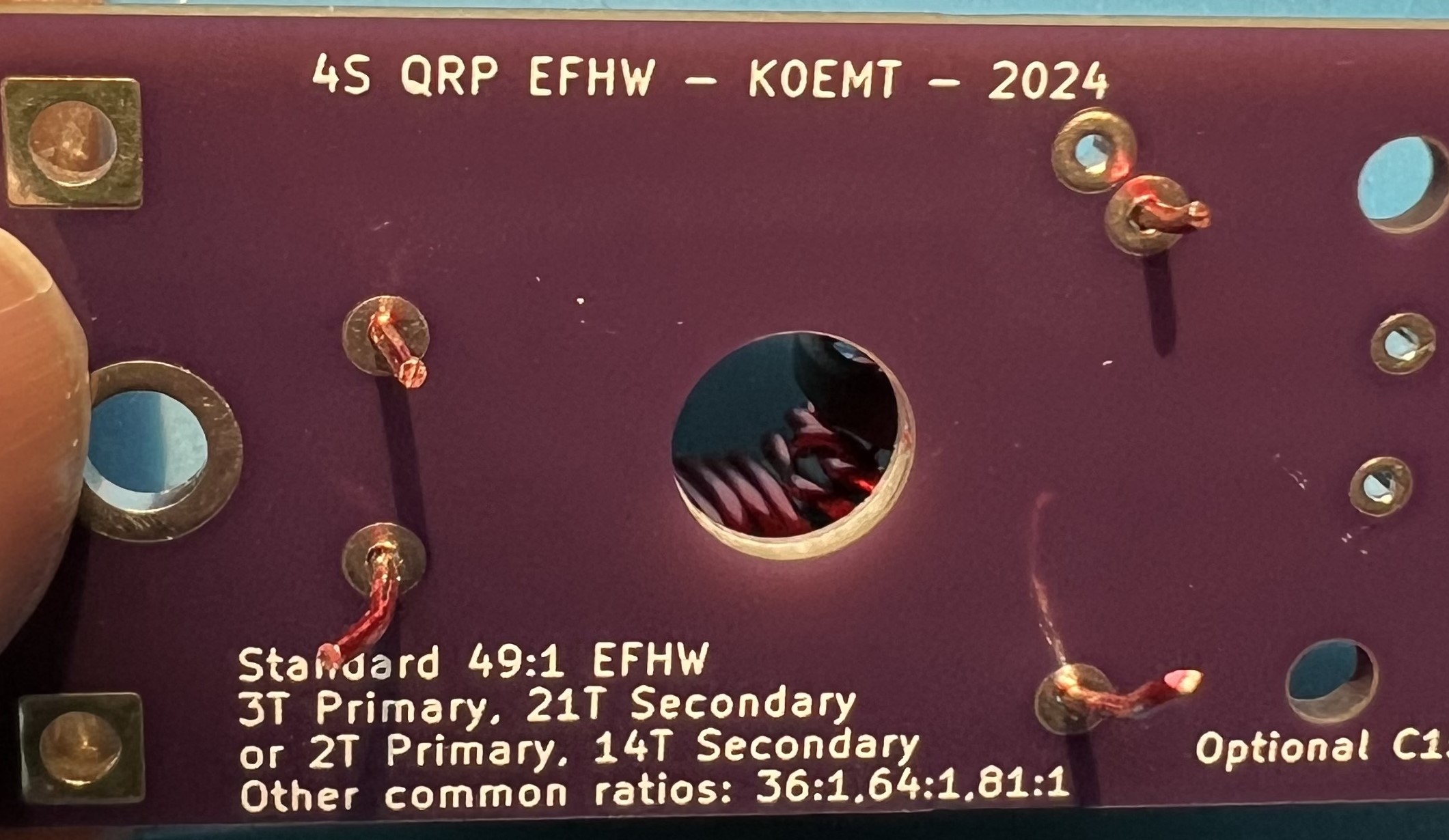
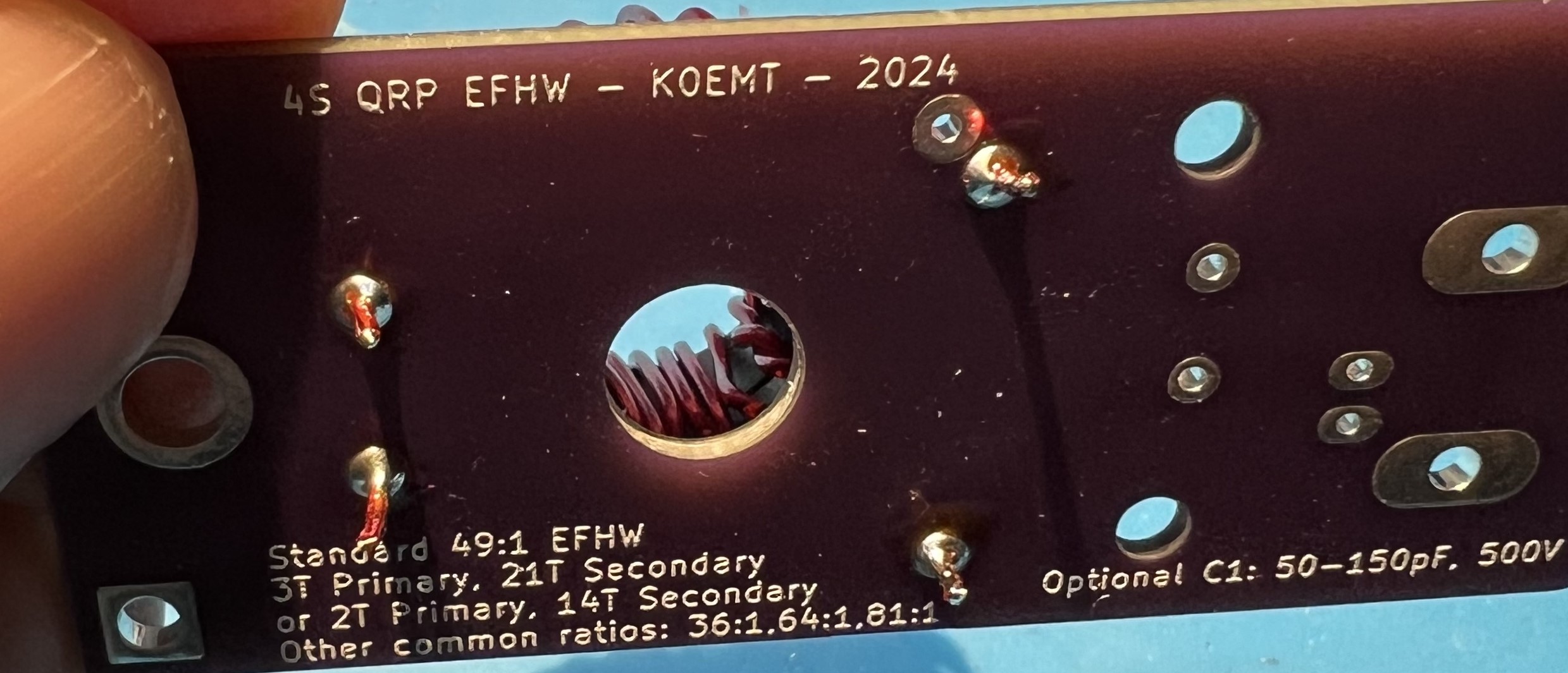
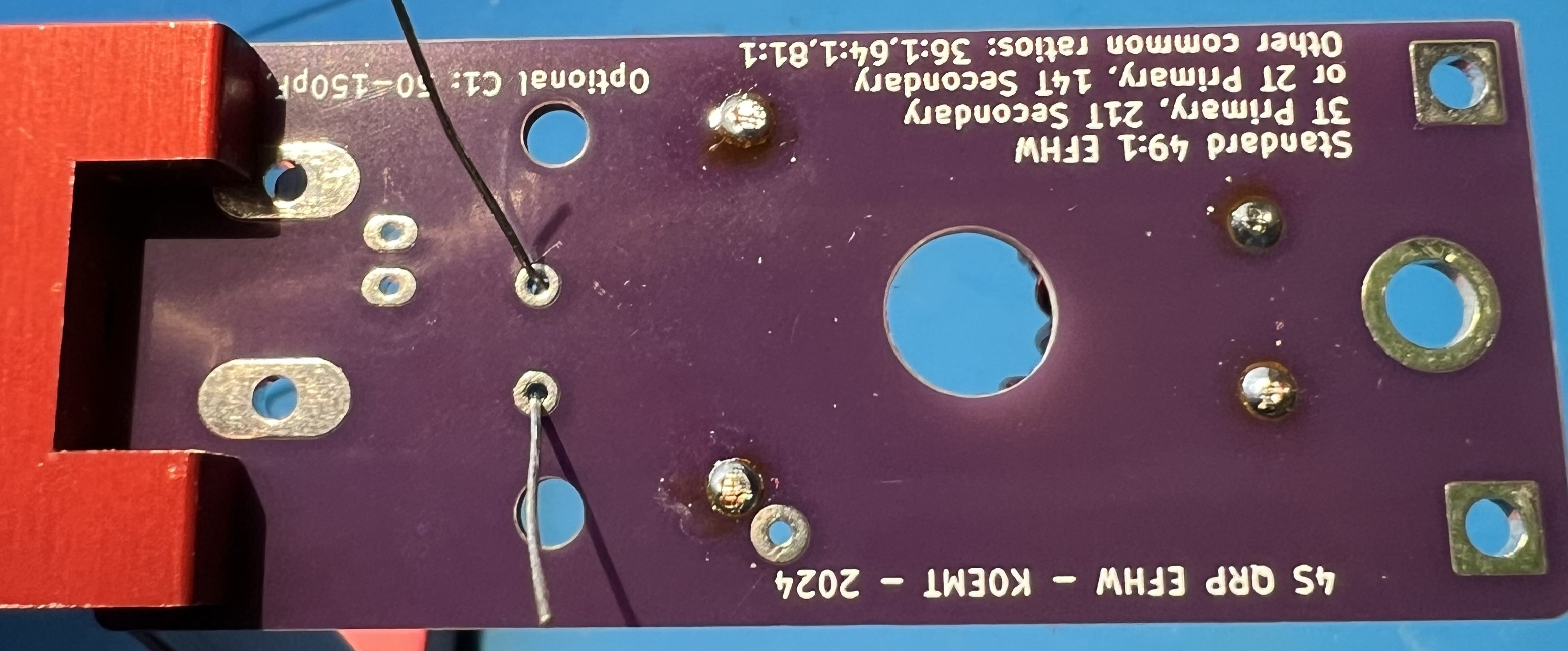
The holes are labeled G and C, inside the T1 block, near the C1 component box.
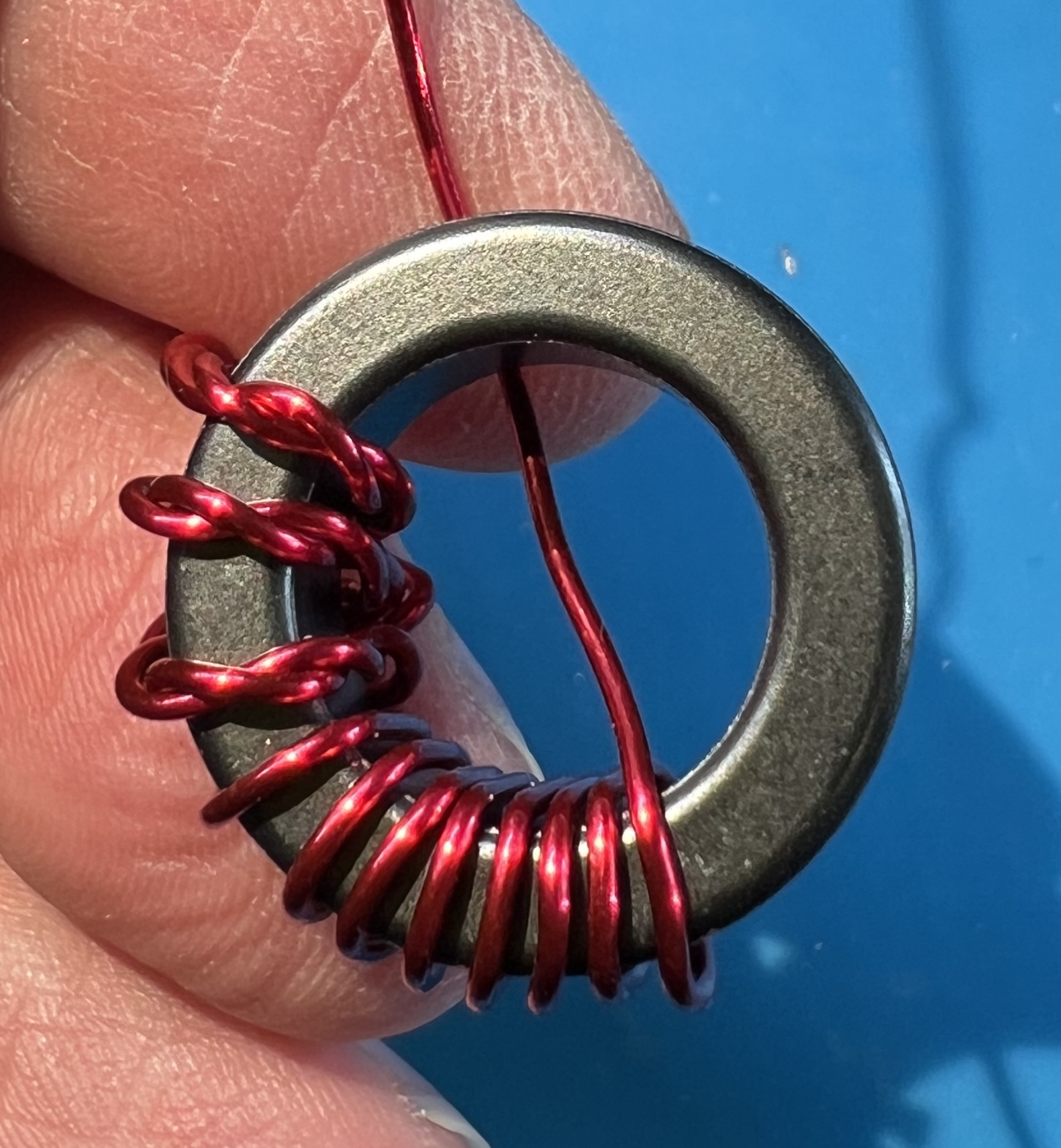
Untwist the wires as necessary so that you can cleanly reach the holes and with the other longer wire continue wrapping the secondary.
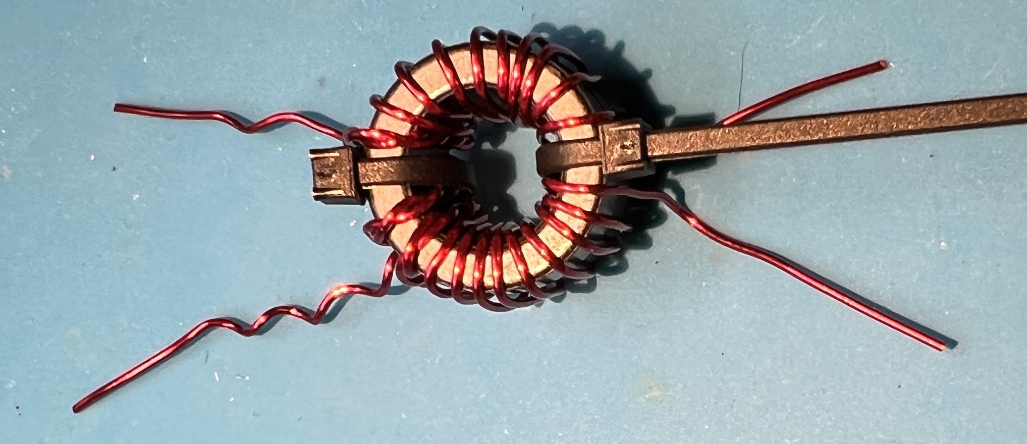
The untwisted primary that goes into the C hole and the continued counter-clockwise secondary winding.
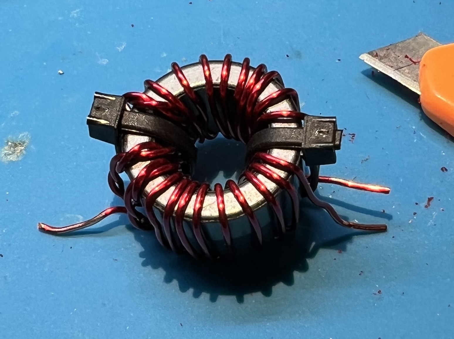
You should count from the center double wrapped wire of the primary, counterclockwise the wire passing through the center of the toroid 11 times.
That will be the middle twisted wire and one more twisted wire to the right.
Followed by 9 more turns of single secondary wire.
Now, do the same thing but continuing clockwise.
Start from the middle winding of the twisted wires.
Count it and one more twisted to the left.
Now wind 9 more to the left.
In total you will have 21 windings.
But, we counted 11 twice you protest!
Well, that’s because we counted the first winding (the middle winding) each time.
Now is a good time to give yourself a pat on the back or take a break.
Placing and soldering
Place the prepped transformer against the board.
Line up the wires against the through holes.
Verify you can get the wires in the holes.
Trim the wires, but leave some excess.
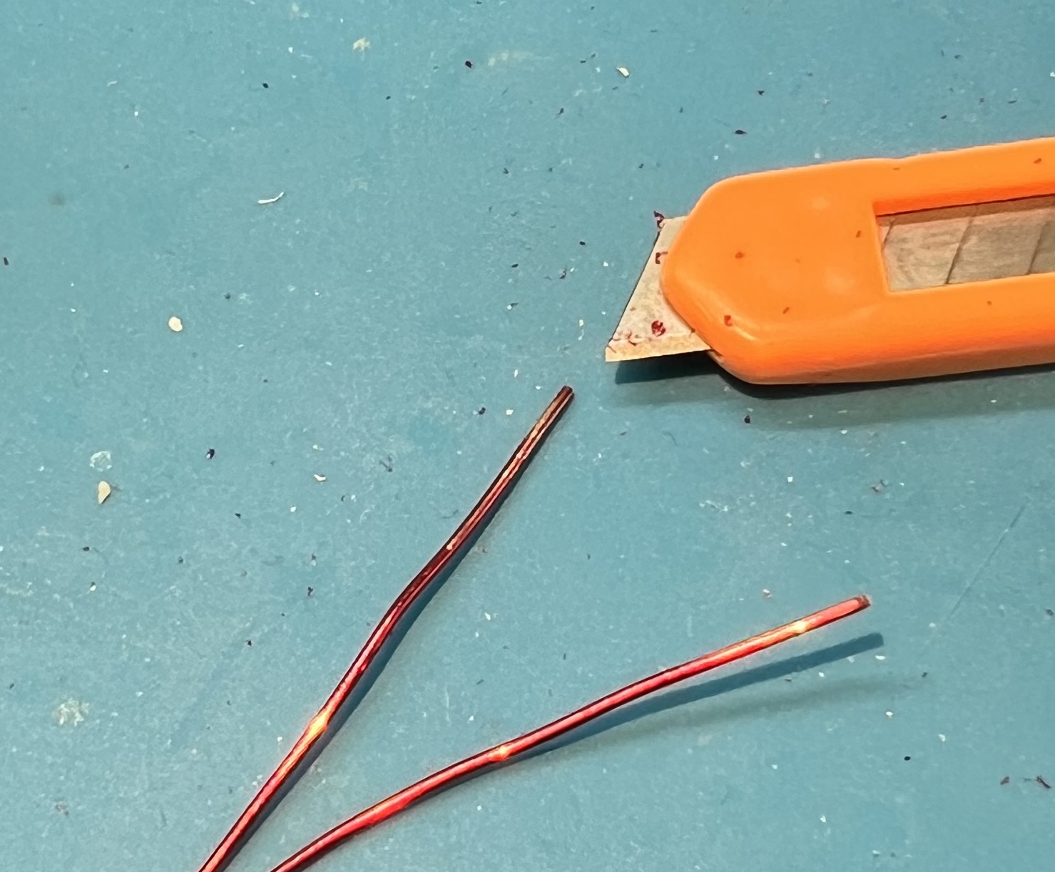
Use a utility knife to remove enamel coating from the wire where you will be soldering.
I like to use a technique of holding the blade at a 45 degree angle against the wire.
Then either work the blade against the wire, or hold the blade and pull the wire.
You will need to be very careful to not nick or damage the wire itself.
Remember to rotate the transformer so that you can scrape all around the wire where it will be soldered.
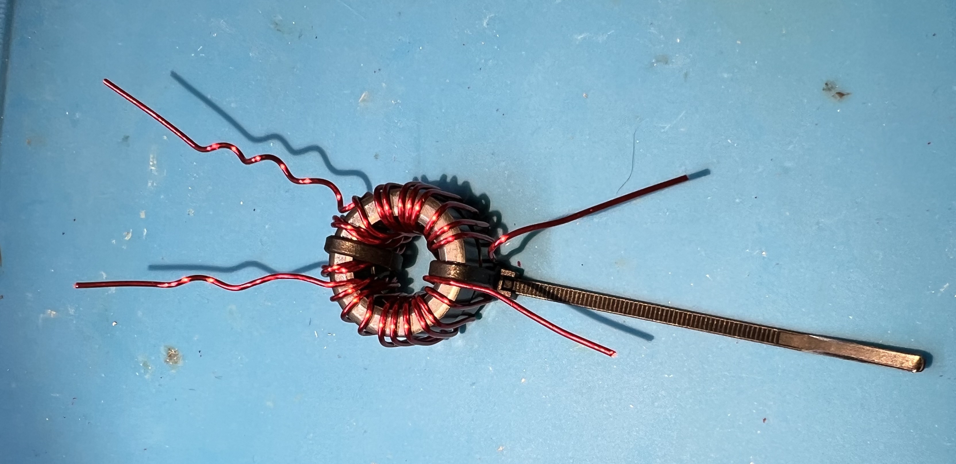
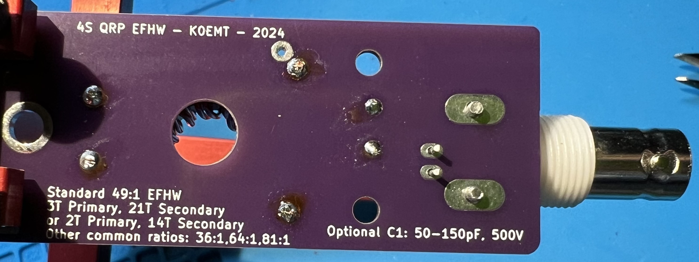
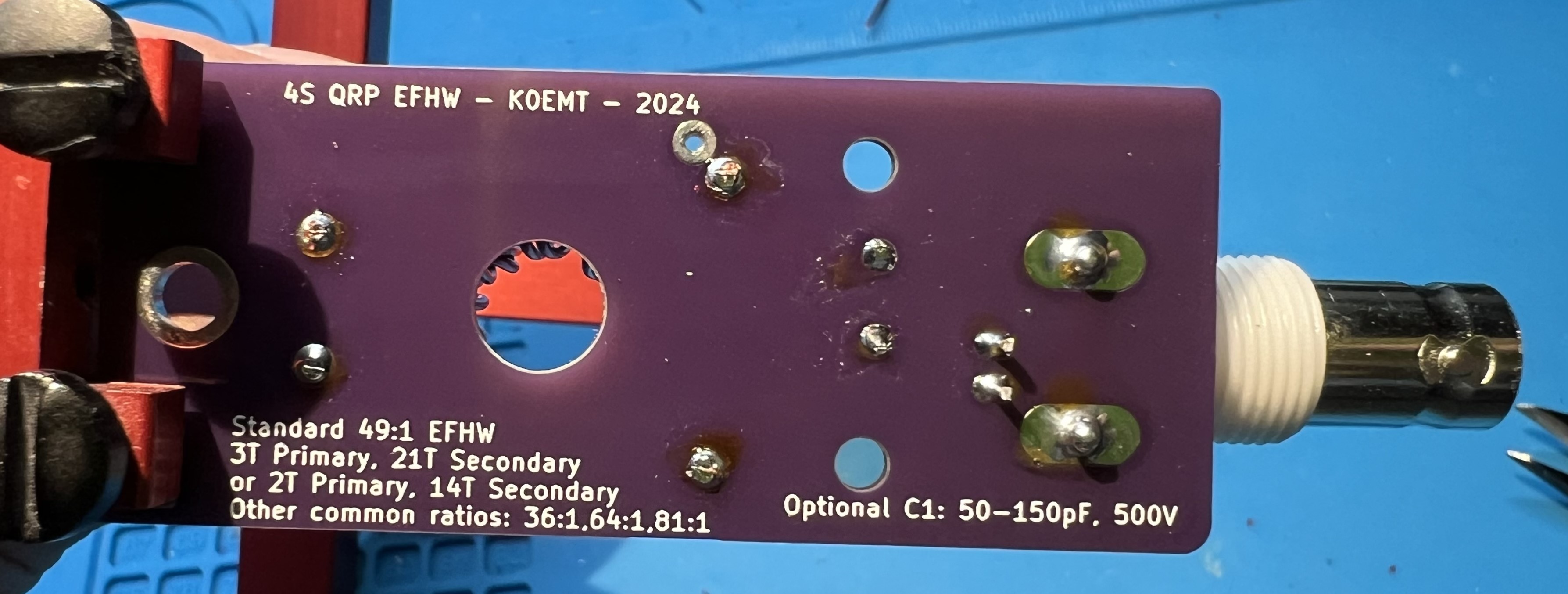
Get the primary side of the transformer into position.
Get lengths and routing checked for the secondary side of the transformer.
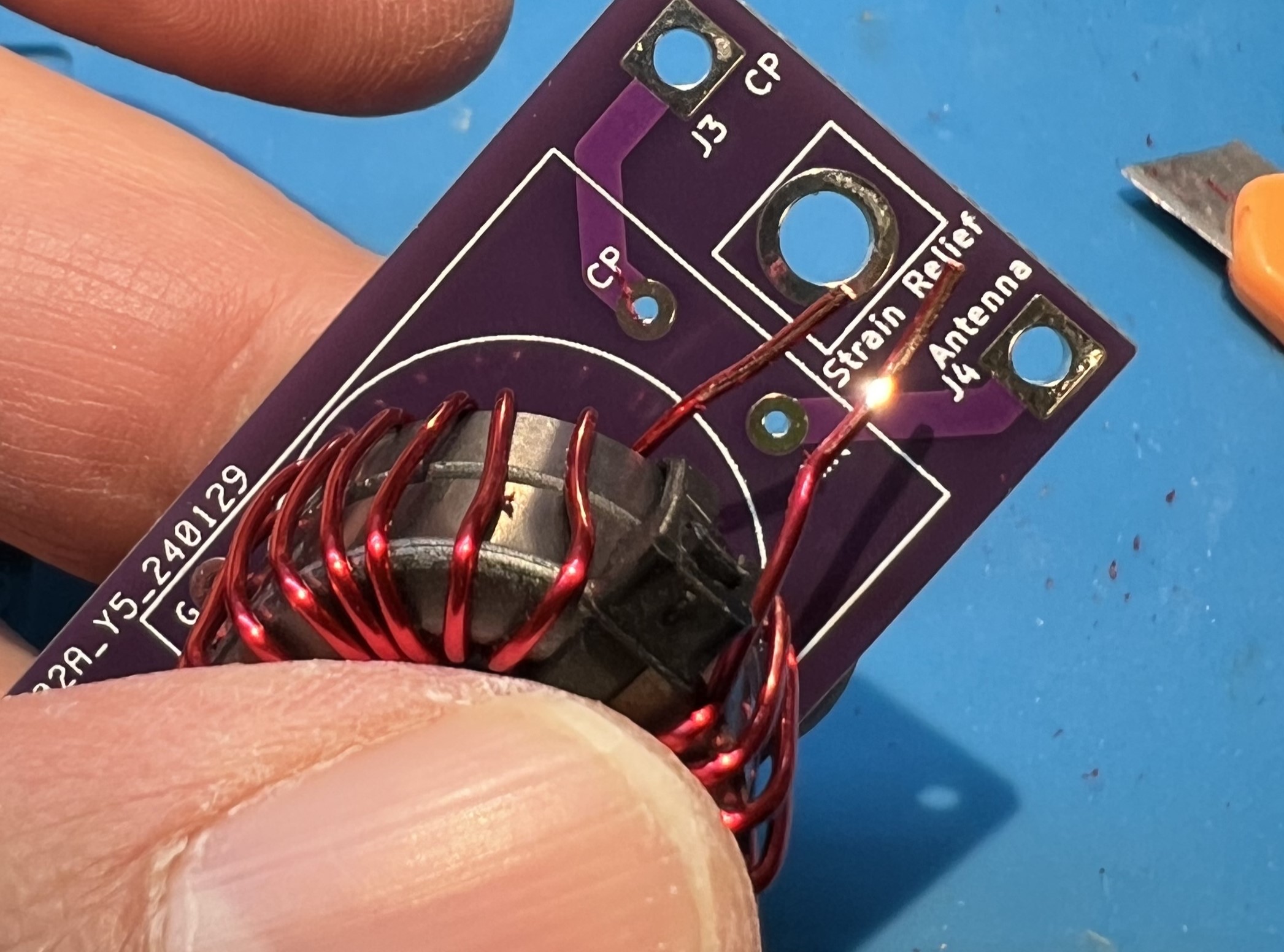
Note the bend you’ll need to get the CP end of the secondary transformer in to place.
Mini pliers can help with this.
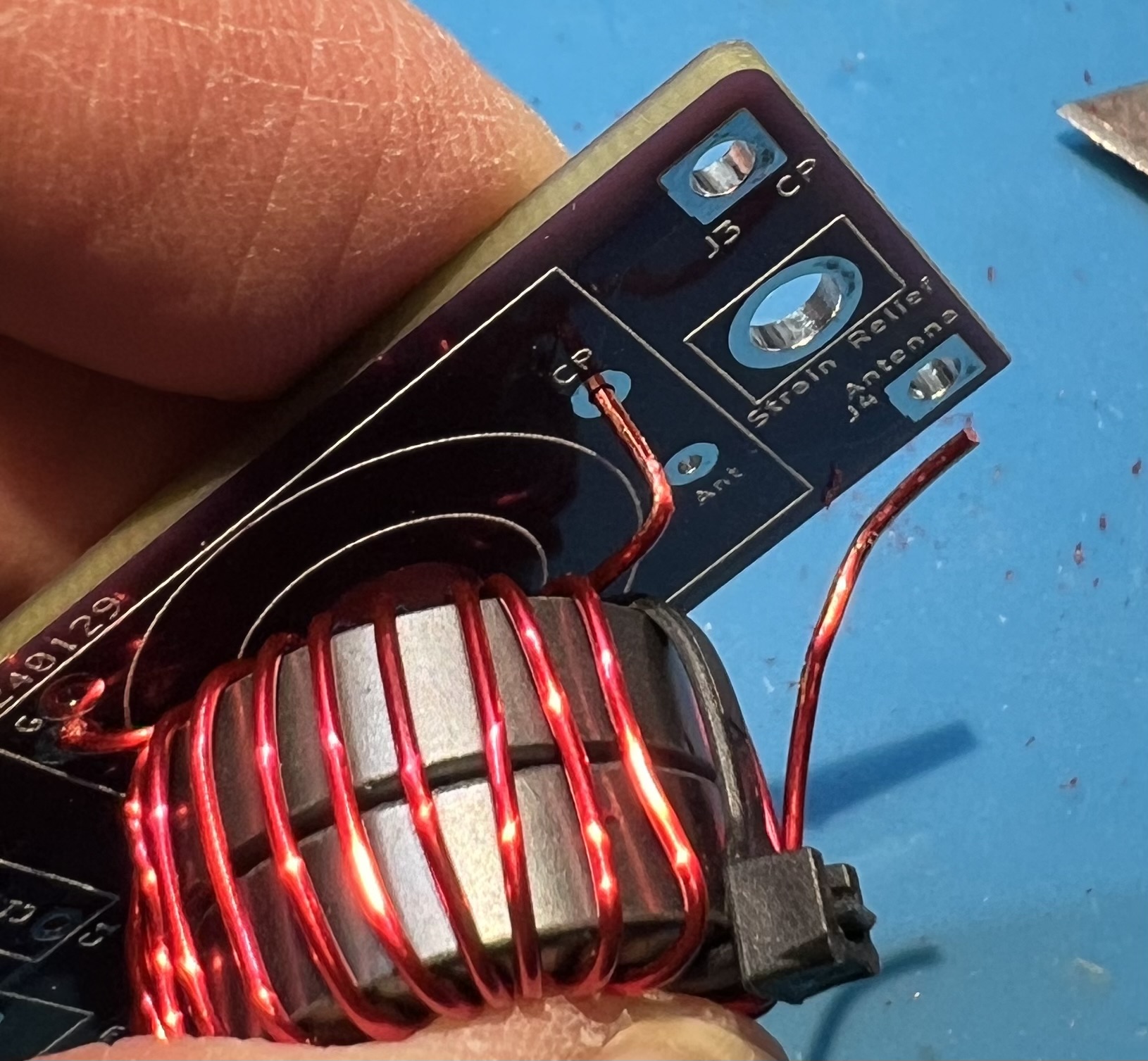
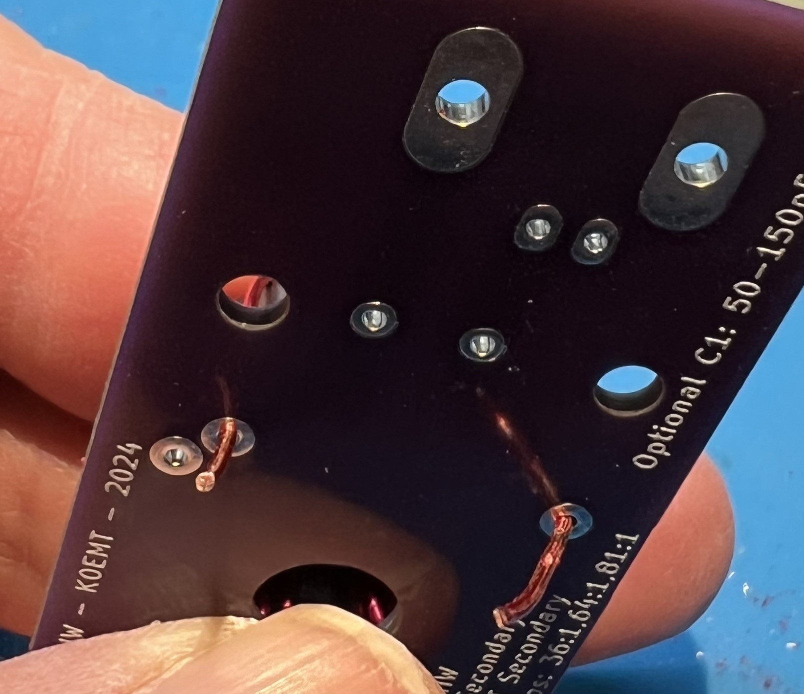
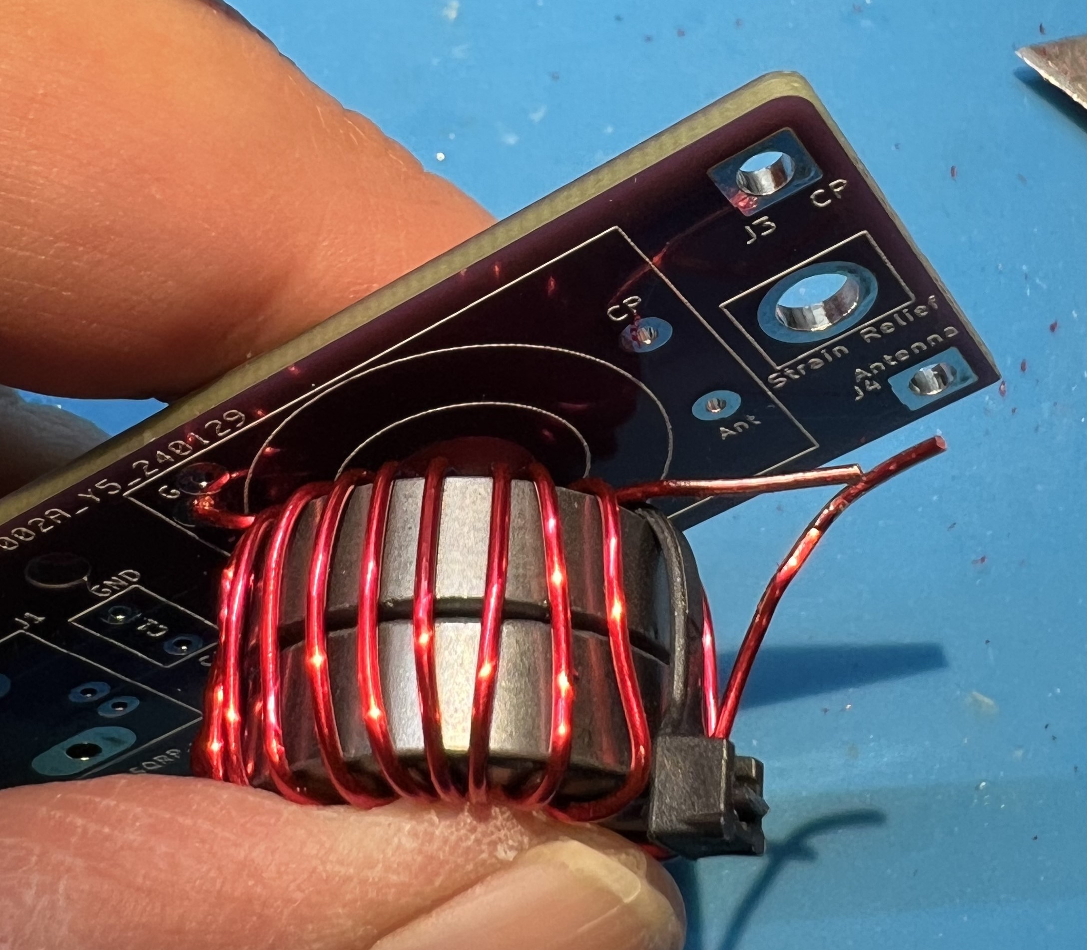
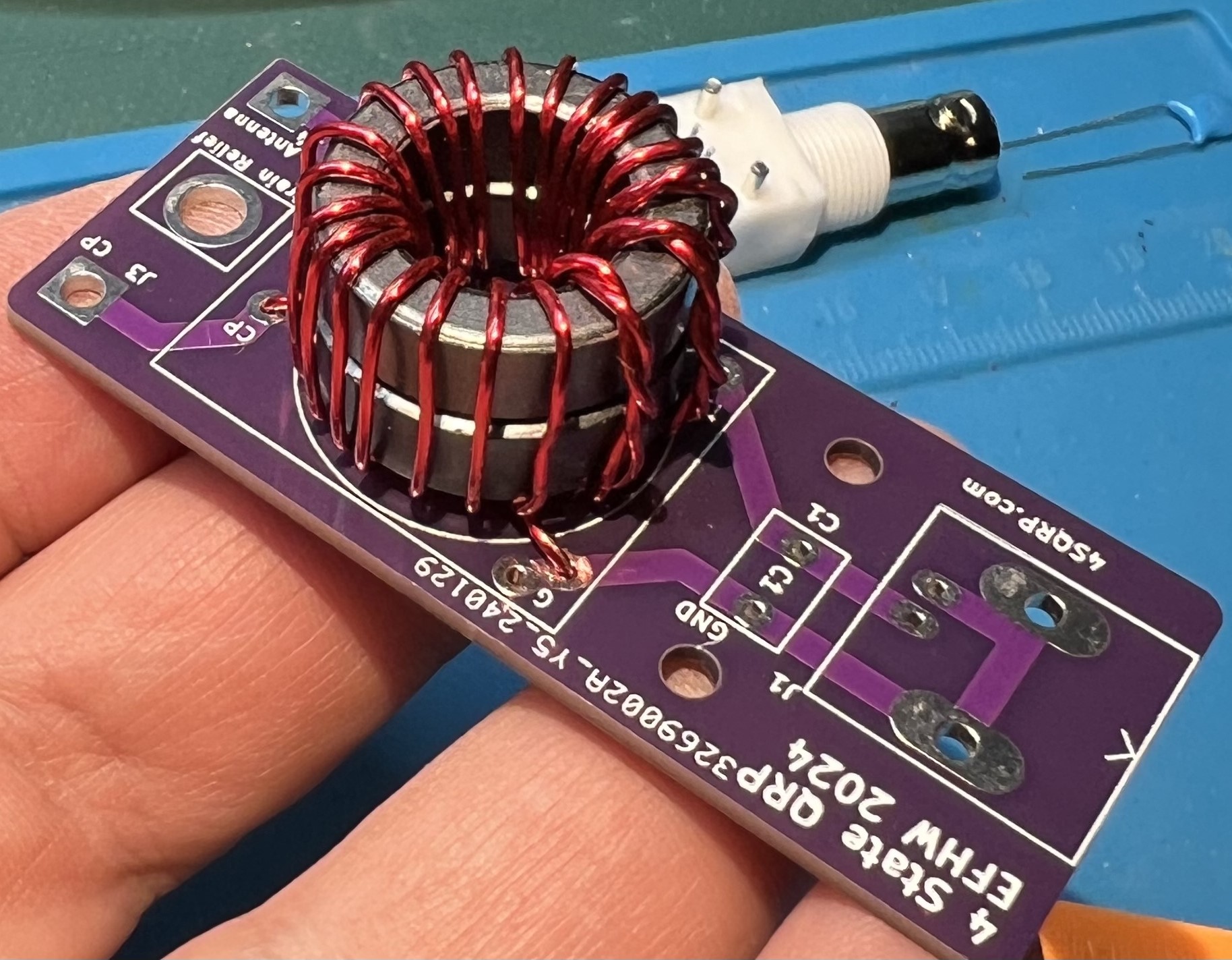
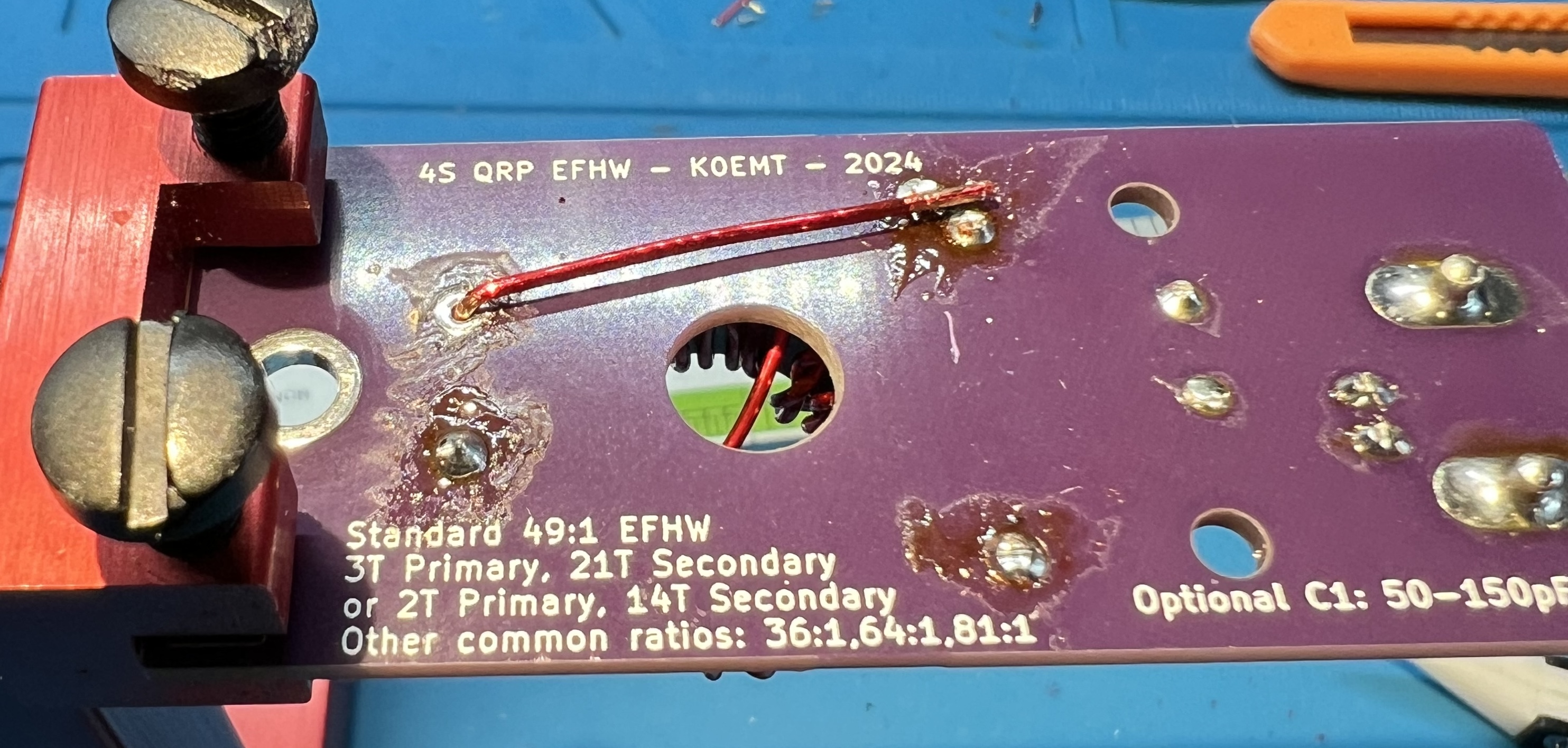
View the transformer leads from the underside of the board.
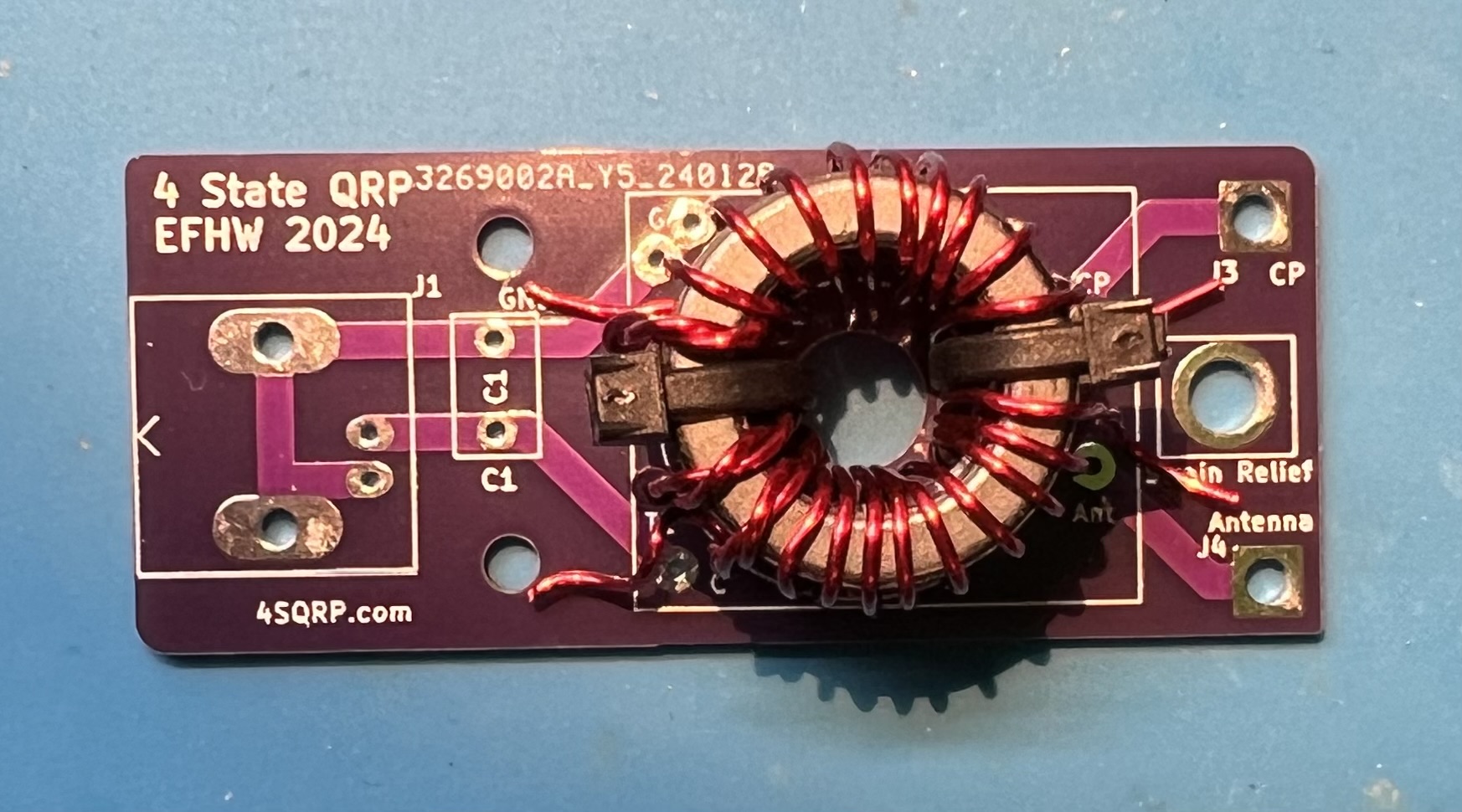
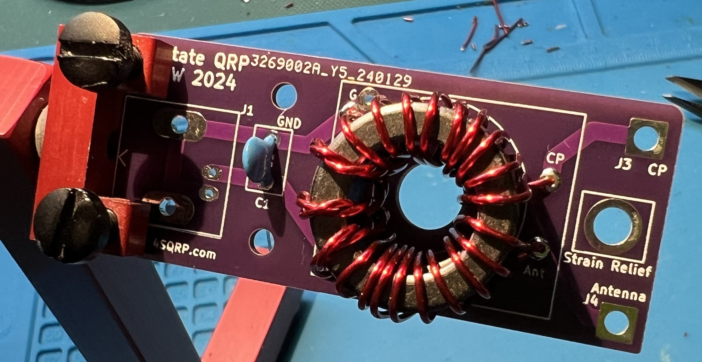
The transformer placement viewed from above and primary side.
NOTE: at this time the zip ties have been removed.
Wire leads trimmed a bit more, ready to solder.
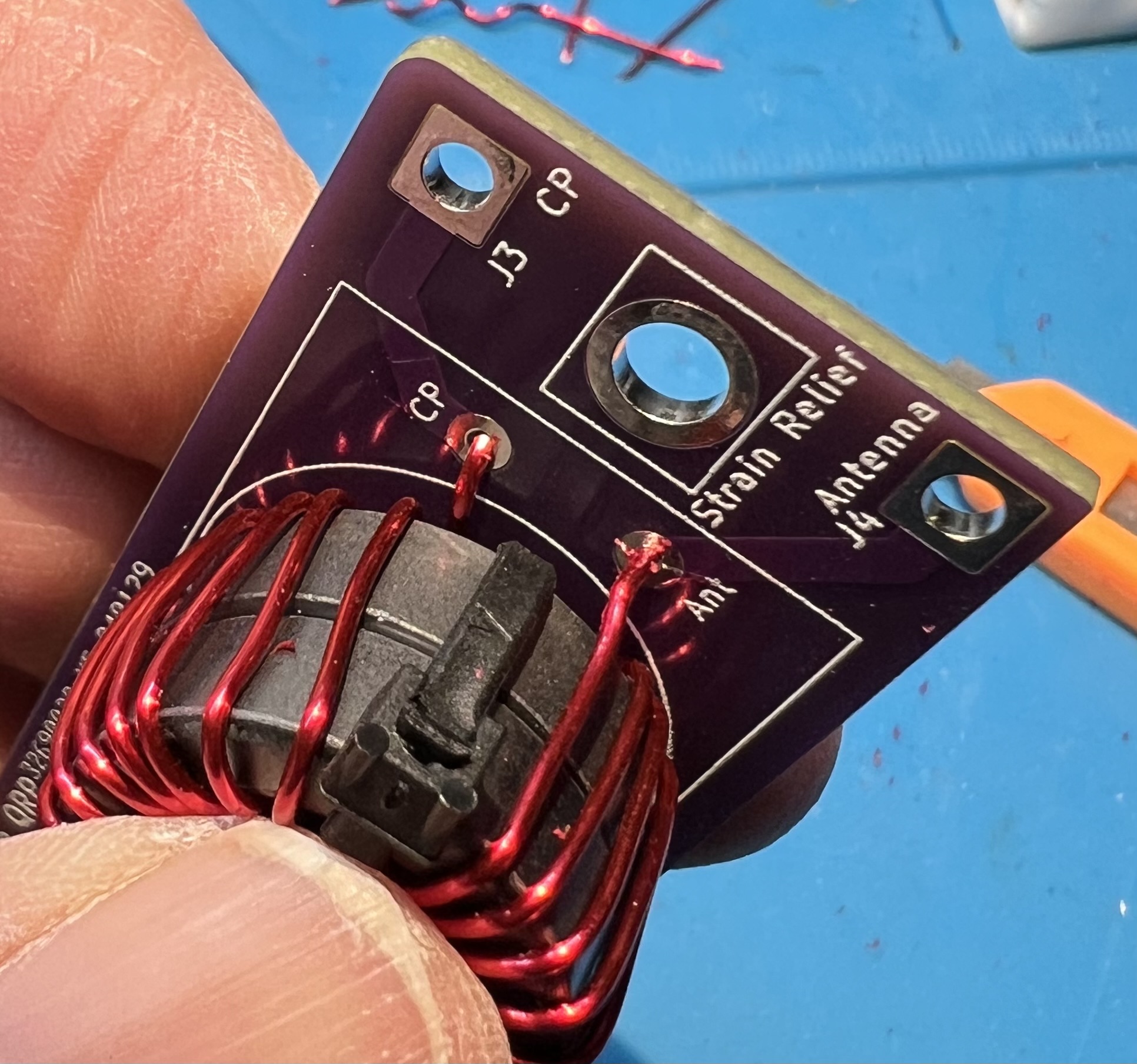
Avoid overheating the wire and melting enamel further up into the toroid.
Note that the blue surface pictured here is a heat resistant silicone mat.
Note that the solder is covering the pad and the wire where the enamel coating was removed.
Testing
Test for good continuity on the secondary winding. Use an ohm meter to check for continuity between J3 CP and J4 Antenna on the output side.
If you don’t have continuity, that means you didn’t get the enamel off of the wire at the through holes of the secondary.
Inspect and correct wires at CP and Antenna in the transformer block.
Check for continuity between the BNC mount holes and the secondary side CP and Antenna connections.
You should not have continuity here.
If you do have continuity, that means you have somehow shorted the primary and secondary wires.
You will most likely need to remove the windings and restart with new wire.
Flip the board over and test for continuity in the capacitor block C1. You should have continuity when you place your leads here. If you don’t have continuity, that means you didn’t get the enamel off of the wire at the through holes of the primary. Inspect and correct wires at G and C in the transformer block.
Wrapping up
Trim leads.
Solder the capacitor in place now.
Solder the BNC in place now.
Use a spudger to spread the transformer turns both inside and around the core.
The spudger is plastic and is used to avoid damaging the wire or the enamel coating.
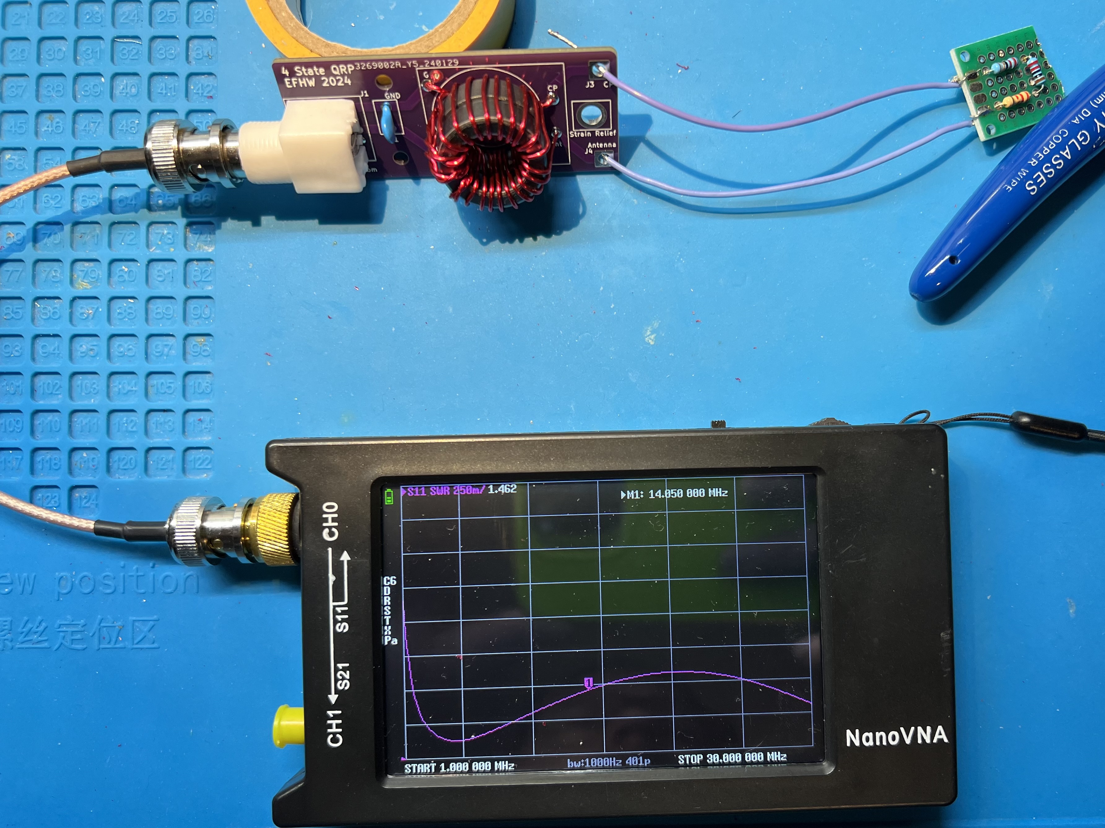
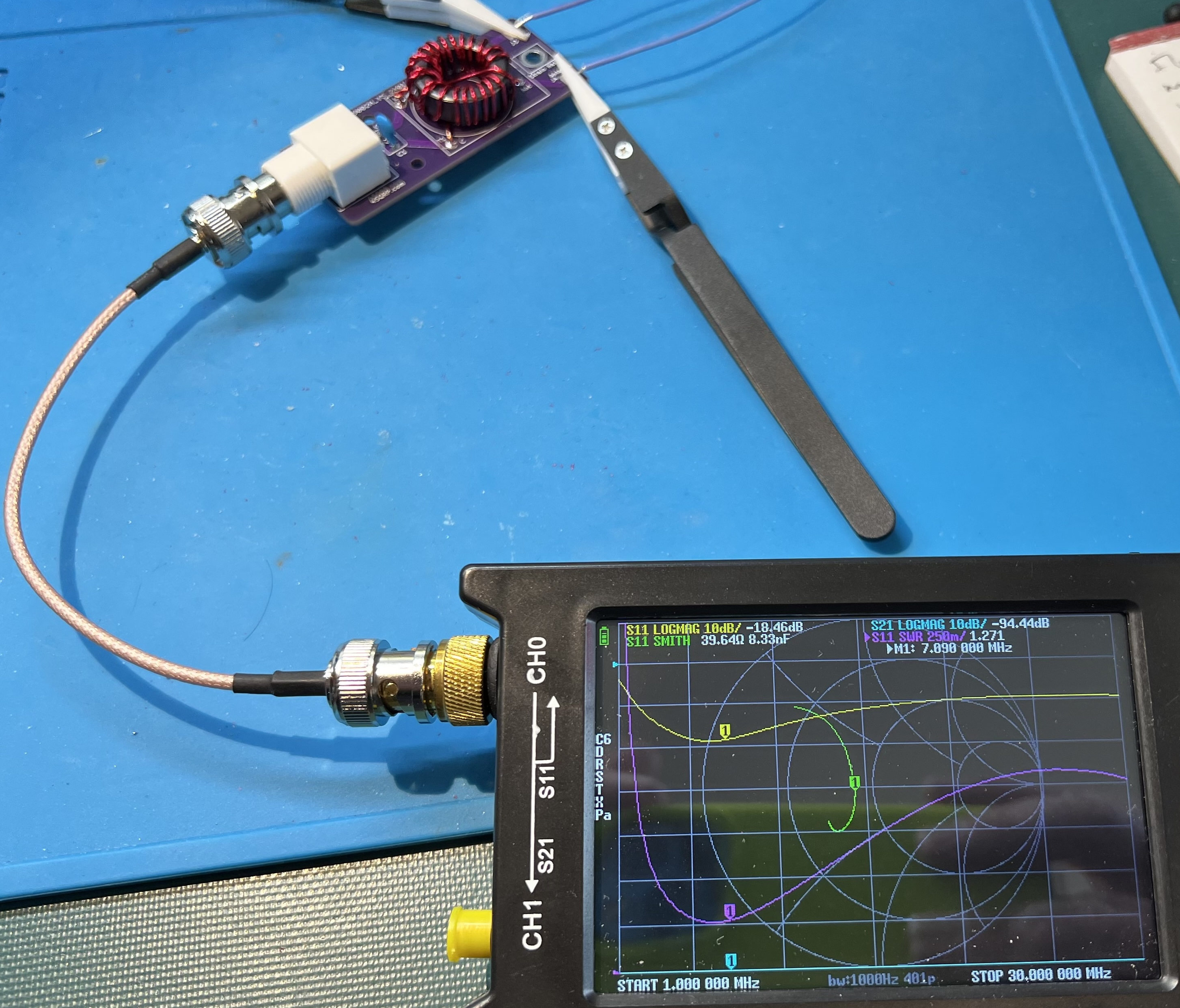
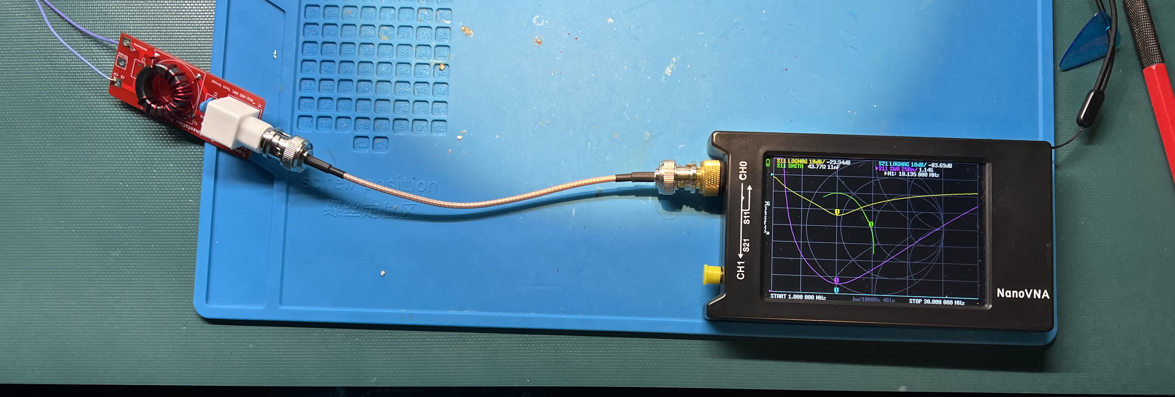
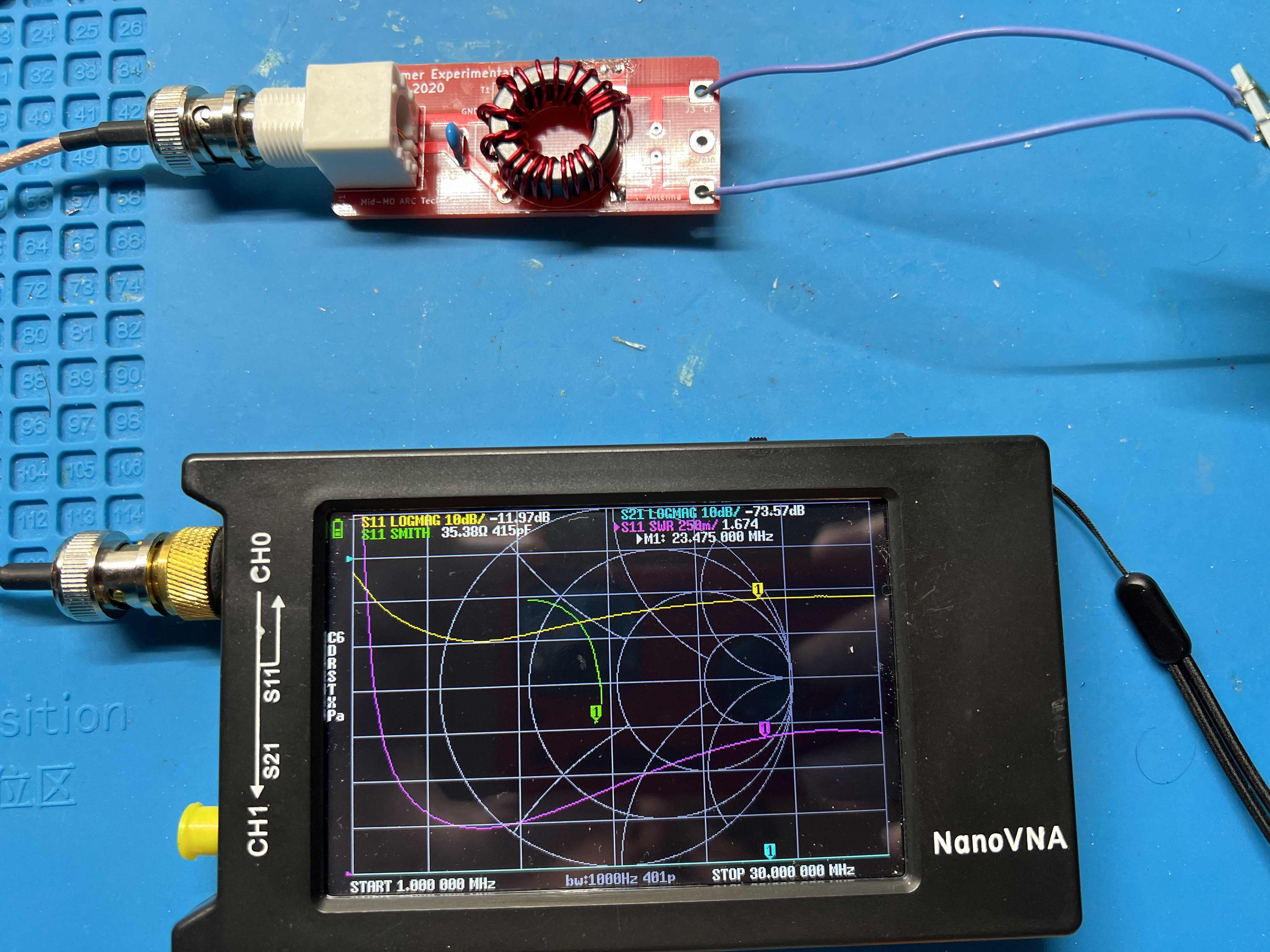
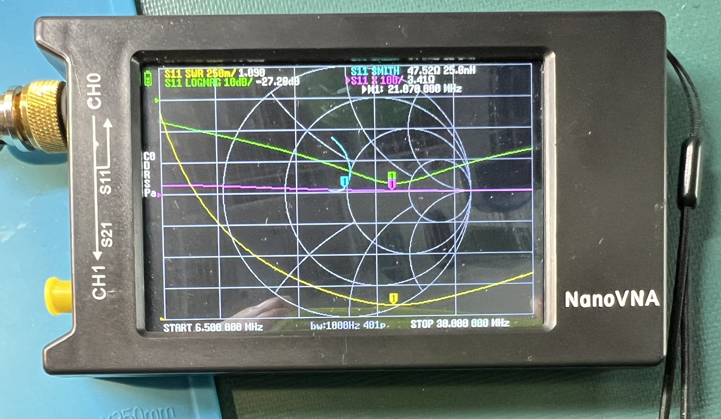
Transformer with a resistive test load and a nanoVNA showing SWR plot.
Single Toroid
Use 20awg enamel coated wire. Use the same assembly approach as with the double stack. However, with a single toroid, the Primary has 4" of wire, and the secondary uses 20" of wire. The twisted section will be a bit over 3" in length.
Shared Ground
Uses the same lengths of wire for single or double stack configuration.
Prepare the wire ends.
Slightly offeset the end of the twisted pair.
The twisted section will be a bit over 3" in length.
Wind onto the core in a counter-clockwise fashion.
Cross over the core at turn 11.
Remove the enamel from the wire where it will be soldered.
Solder the primary side wires. You will also solder the ground side of the secondary at this time.
Make a wire jumper to connect from the G pads in the toroid block over to the CP pad.
You may consider soldering this ground jumper in at the same time as the primary and secondary grounds.
I ended up soldering the jumper at the CP pad on both the top and bottom of the board.
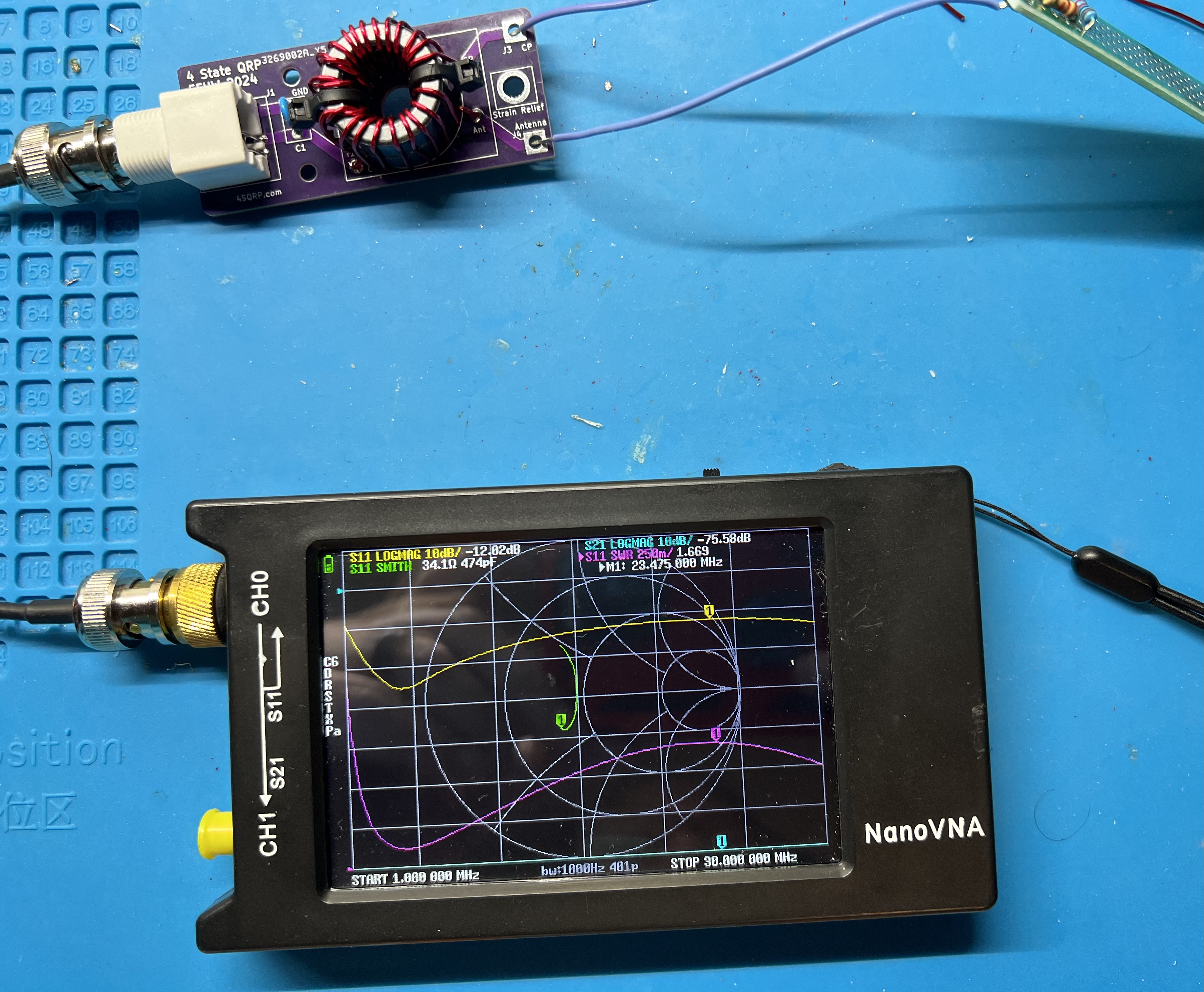
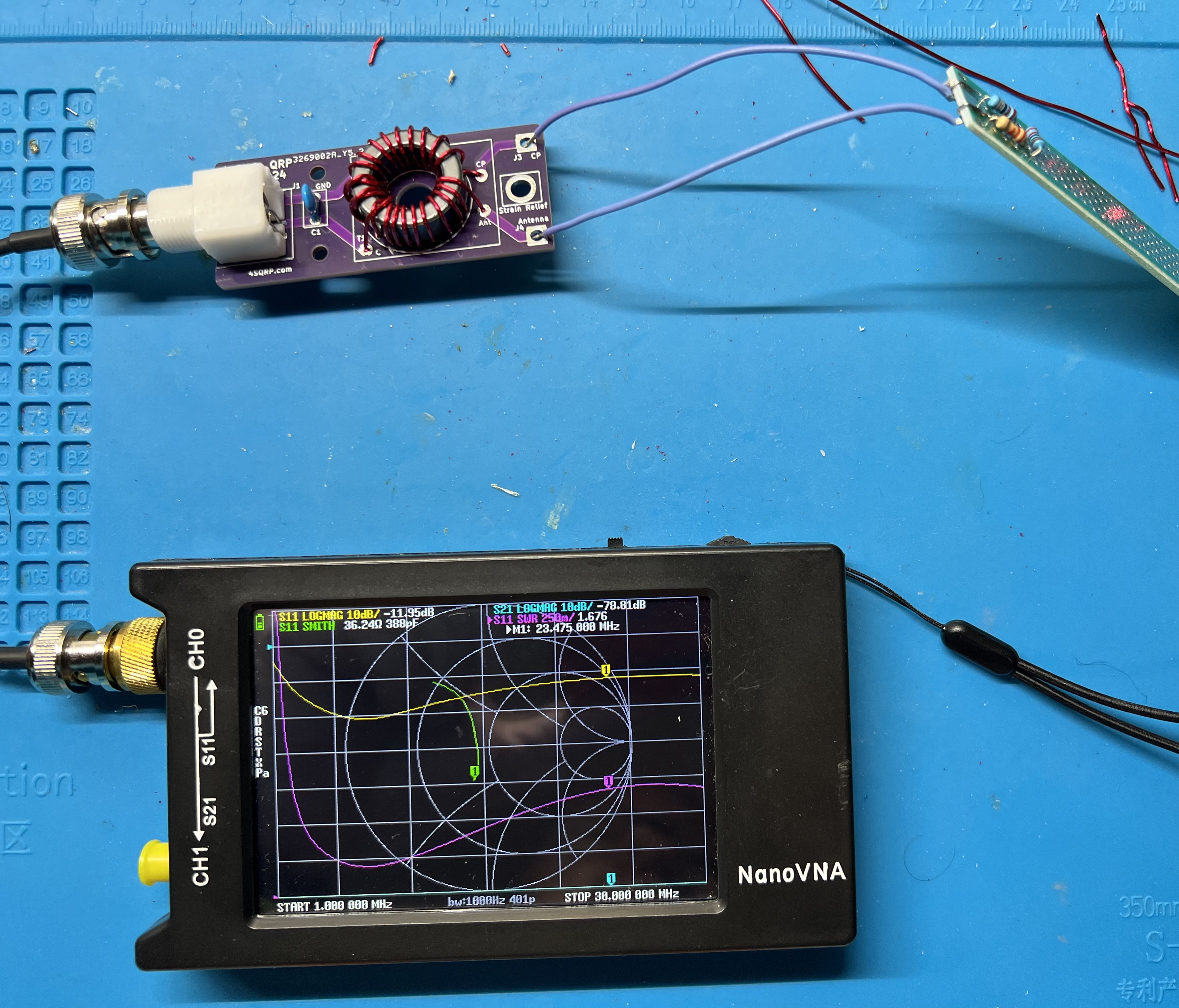
Checking the completed board with a nanoVNA.
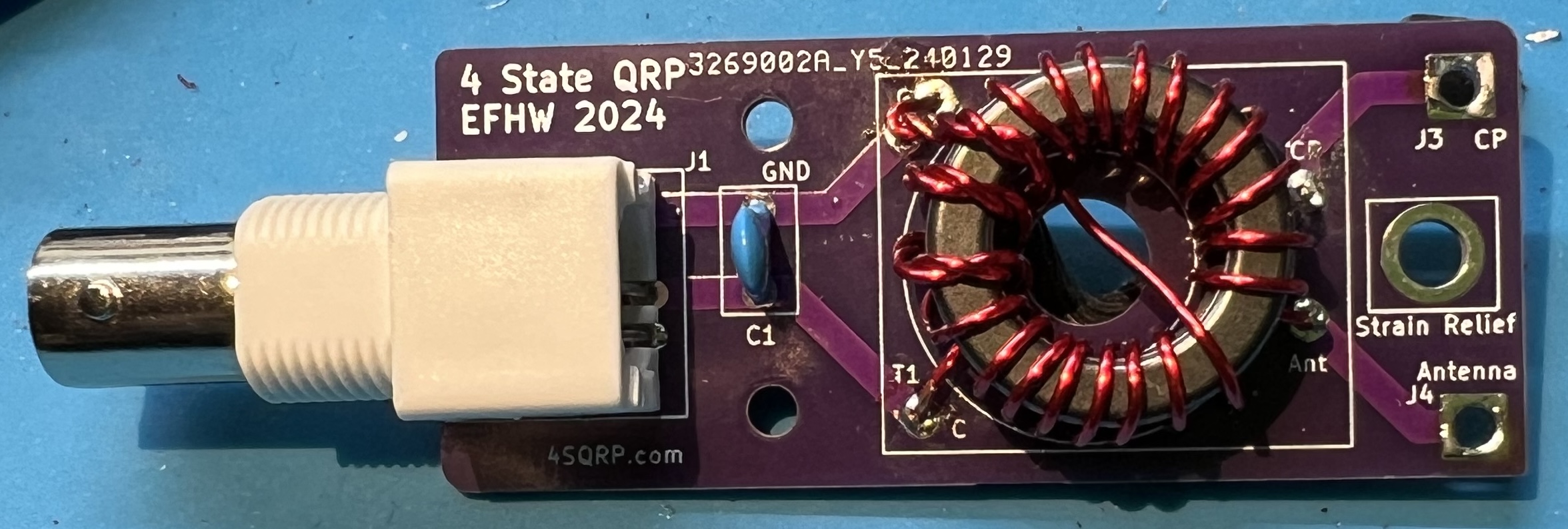
The completed board.
Theory
Windings
When you see a notation like 2:14 and 3:21 that means how many turns on the primary and how many turns on the secondary part of the transformer. 2:14 means 2 turns on primary, 14 turns on secondary. Likewise, 3:21 means 3 turns on primary, 21 turns on secondary.
So, where does the 49:1 come from? That is the transformation ratio. To arrive at it we consider the ratio of turns on the secondary to the primary. With a 2:141 this becomes 14 to 2 or 7 to 1. Take the 7 and square it to arrive at 49:1. We’re transforming a roughly 2450 ohm feedpoint down to 50 ohms.
Other common ratios that are used with EFHW antennas are 36:1, 64:1, and 81:1. Respectively ratios of 6:1, 8:1, and 9:1. To make a 36:1 transformer you could have a 3 turn primary, and an 18 turn secondary.
Note: In these pictures, they are all 49:1 transformers.
Original 4S QRP Experimenter PCB 2:14
Original 4S QRP Experimenter PCB 3:21
2024 EFHW board with Double Stack FT82-43 toroids, 3:21
2024 EFHW board with Single Stack FT82-43 toroids, 3:21
Transformer Theory
The 100pF capacitor is often added to the primary side of the transformer in an End Fed Half Wave (EFHW) antenna for a couple of reasons:
-
Improves Higher Frequency UNUN Performance: The capacitor can help improve the performance of the Unbalanced to Unbalanced (UNUN) transformer at higher frequencies2,3.
-
Compensates for UNUN Primary Leakage: The capacitor can help compensate for any leakage in the primary of the UNUN2.
-
Flattens SWR at Higher Frequencies: The addition of the capacitor can help flatten the Standing Wave Ratio (SWR) at higher frequencies2. This is particularly noticeable for frequencies above 20 meters2.
It’s important to note that the specific impact of the capacitor can depend on the bands you are interested in. For instance, if you’re building an antenna for the 40m band, you might not need the capacitor. But if you’re also using the 20m band, the capacitor can be quite beneficial4.
Please note that these are general observations and the actual impact can vary based on specific antenna designs and operating conditions. It’s always a good idea to experiment and see what works best for your specific setup2,4.
Does the antenna system need a counterpoise? There is always one present. With end fed antennas you also need to watch out for common mode current (CMC) on the feedline.5
Primary Source: Conversation with Bing, 3/20/2024
Antenna Length
An end fed half wave antenna is a half-wave length long and is fed from the end as the name implies. So, determine your wire length by first considering the lowest band you want to work on. For example, 40m, or around 7.030Mhz. Then use the standard dipole formula of 468 / frequency = feet. So, for our example, 468 / 7.030 = ~66.57ft or ~66 feet and 7 inches. As the adage goes it is easier to trim wire than add it. Therefore, I would start with ~70ft of wire and adjust back from there. A simple thing to try is to fold the wire back on itself at the end.
The normal dipole like radiation pattern for the EFHW is when it is being used on it’s primary band. You will have more lobes on the usable or harmonic bands. With more lobes the further you get from the primary band.
You will most likely need to use some small amount of tuning when using the antenna portable or on non-primary bands.
| Primary Band | Usable bands | Initial length |
|---|---|---|
| 160m | 80m, 40m, 20m, 15m, 10m | 265' |
| 80m | 40m, 20m, 15m, 10m | 135' |
| 40m | 20m, 15m, 10m | 70' |
| 20m | 10m | 35' |
-
https://noji.com/hamradio/pdf-ppt/noji/Noji-Article-80-10-EF-HW.pdf “80-10 end-fed half-wave antenna with 49:1 unun - Noji.” ↩︎
-
https://www.ai6xg.com/post/efhw-xfrmr-capacitor “End Fed Half Wave Antennas: Is a Primary Capacitor Really Needed?” ↩︎ ↩︎ ↩︎ ↩︎ ↩︎
-
https://www.ai6xg.com/post/end-fed-half-wave-antennas-more-about-the-primary-capacitor “End Fed Half Wave Antennas: More About the Primary Capacitor.” ↩︎
-
https://dxexplorer.com/49-1-impedance-transformer/ “49:1 Impedance Transformer for EFHW Antenna - DX EXPLORER.” ↩︎ ↩︎
-
https://www.radio-stuff.com/post/do-i-need-a-counterpoise-for-your-efhw “Do I need a counterpoise for my EFHW? - M0VUE” ↩︎
2024 EFRW Transformer
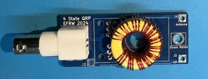
Components
- Bare PCB
- BNC connector
- Toroid T94-6
- 48" of 22AWG enamel coated wire
Tools
- flush cutters
- mini pliers
- utility knife
- ruler
- soldering iron, set to 350C
- spudger
- heat safe work surface (or board holder)
Instructions
Winding the toroid
We will construct a 12 Turn trifilar winding.
- Cut the enamel coated wire into 3 equal lengths of 16". These will be your winding wires.
- Take one length of wire, bend it in half to create a U shape.
- Hook this U shape over the toroid to start your winding.
- Wind each half of the wire around the toroid.
- Each pass of the wire through the toroid counts as 1 turn.
- You want 12 turns around the toroid with each wire.
- Be careful to not scrape off enamel coating when pulling the wire through the toroid.
- Press the wire tightly against the toroid.
- Repeat the above process for each of the two remaining wires.
- These wires should be wound between the turns of the previous wire(s).
- Do not cross the wires over each other. Each wire should have its own separate, parallel path around the toroid.
- Once all wires are wound, double-check your work. You should have 12 turns per wire, for a total of 36 turns.
Testing and soldering the toroid
Construction and testing:
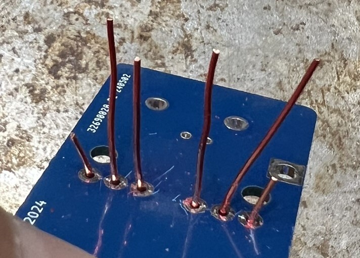
- Feed the ends of the wires through A1, B1, C1, and A2, B2, C2 on the other end. DO NOT TRIM the wires yet!
- Remove a bit of the enamel from the ends of the wire. Where the wire is NOT in contact with the through hole it is passing through.
- Use an ohm meter to check that you have continuity between A1 and A2, B1 and B2, and C1 and C2.
- Now, carefully trim the wires, and remove enamel so that the wires will contact the through holes.
- Solder connections.
- Test continuity from BNC center to J4 - Antenna.
- Test continuity from BNC ground to C1 and J3 - CP.
Note: the spudger can be used to evenly space the wire around the toroid.
BNC
- Solder the BNC to the board.
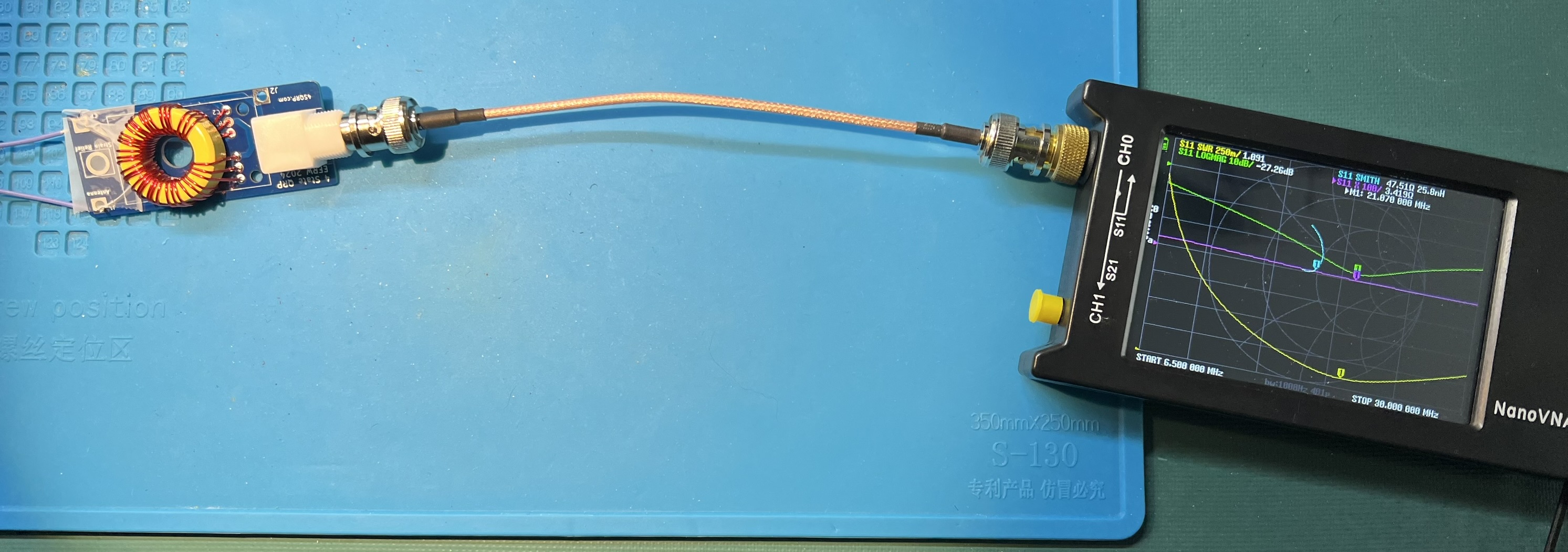
- Check the transformer with a nanoVNA and 450 Ohm resistor.
Subsections of 2024 EFRW Transformer
Theory
Windings
Why a 12 turn instead of a 9 turn? Because of inductance. 9:1 transformers designs are typically presented with T106 or larger transformers. Using the calculator at https://toroids.info I was able to determine that the amount of inductance for 9 turns around a T106-6 is 0.94uH. To approximate that amount of inductance with a T94-6 takes 12 turns to get 1.01uH. The transformer was markedly better with 12 turns versus 9.
Transformer Theory
I like the diagrams on M0UKD 9:1 page. The first shows the physical aspect of the trifilar wound transformer. The second shows the circuit that is being implemented.
Like the EFHW transformer, there is ratio of turns in the primary versus the secondary. In this case we have 3 times the primary in the secondary. Thus it is a 9:1 transformer.
This transformer steps down a 450 Ohm impedence to 50 Ohms.
Antenna Length
The random in end fed random wire antenna is a misnomer. In order for the antenna to work, you must avoid half-wave lengths.
| Antenna Length | CP | Usable bands |
|---|---|---|
| 34’1, 41’, 58' | 13’, 17' | 40-30-20-17-15-12-10 |
| 71’, 84’2 | 17’, 33' | 80-40-30-20-17-15-12-10 |
1 34’, 35’, and 35.5’ are commonly used lengths.
2 84’ antenna with a 17’ counterpoise is a W3EDP antenna.