Double Stack
Winding
Use 20awg enamel coated wire. Primary uses 8" of wire, secondary uses 35" of wire.
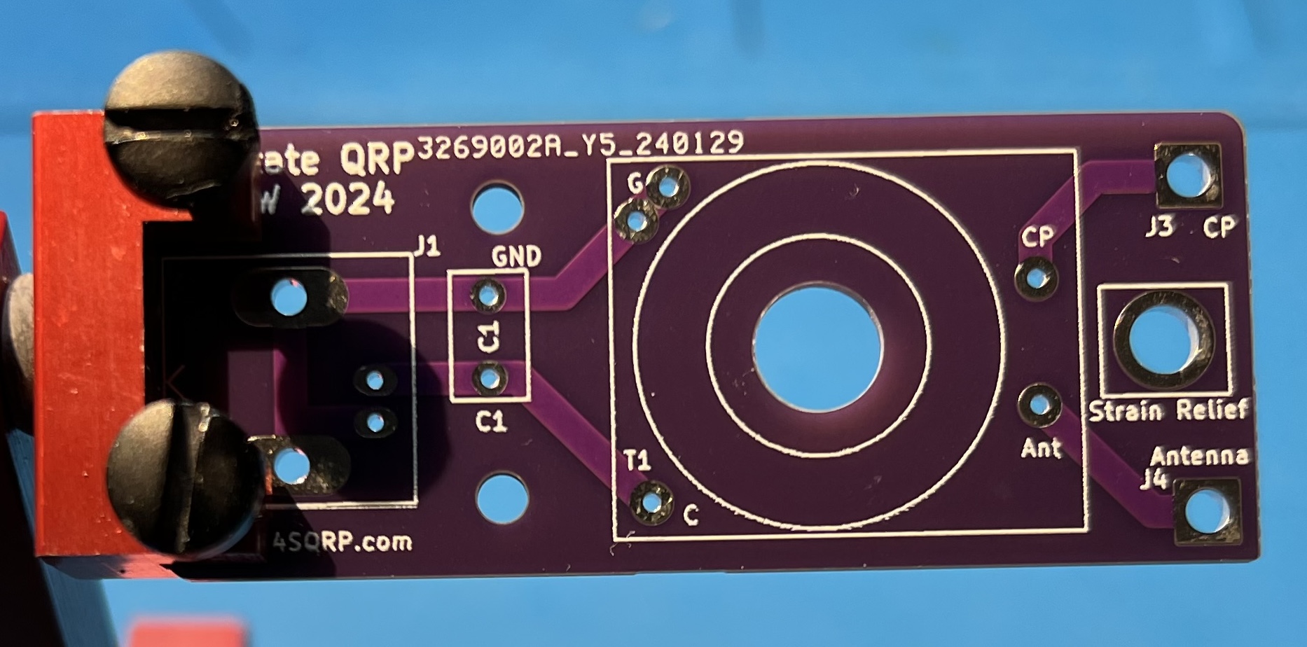
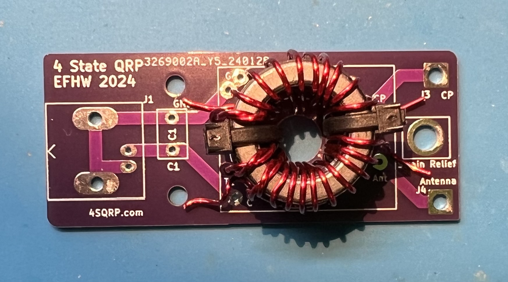
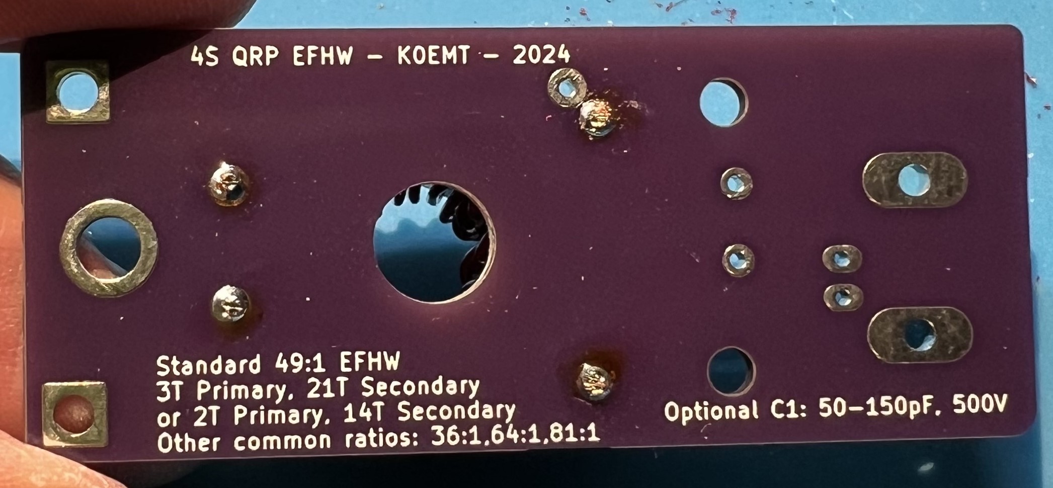
The bare board.
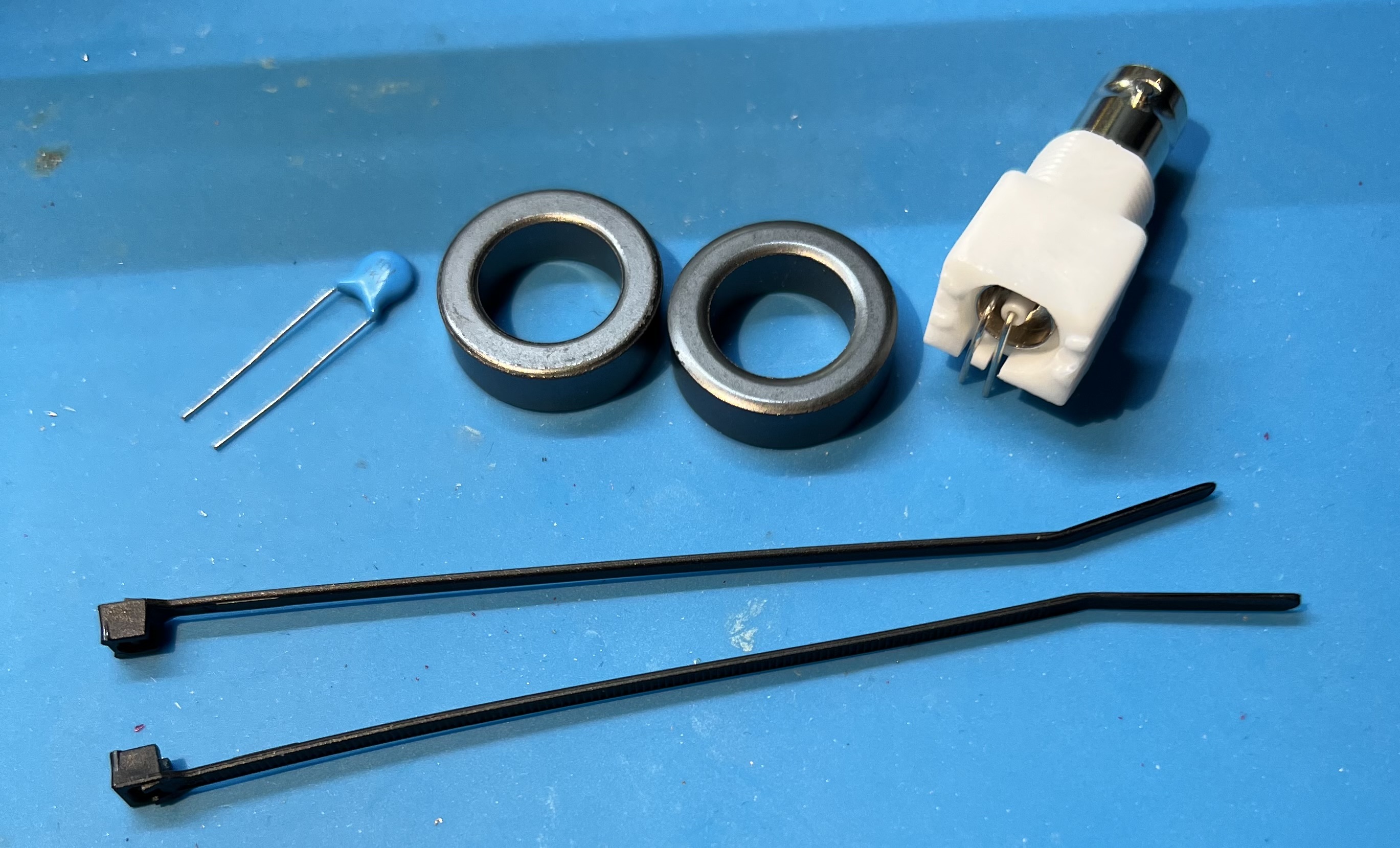
The capacitor, FT82-43 toroids, zip ties, and female BNC.
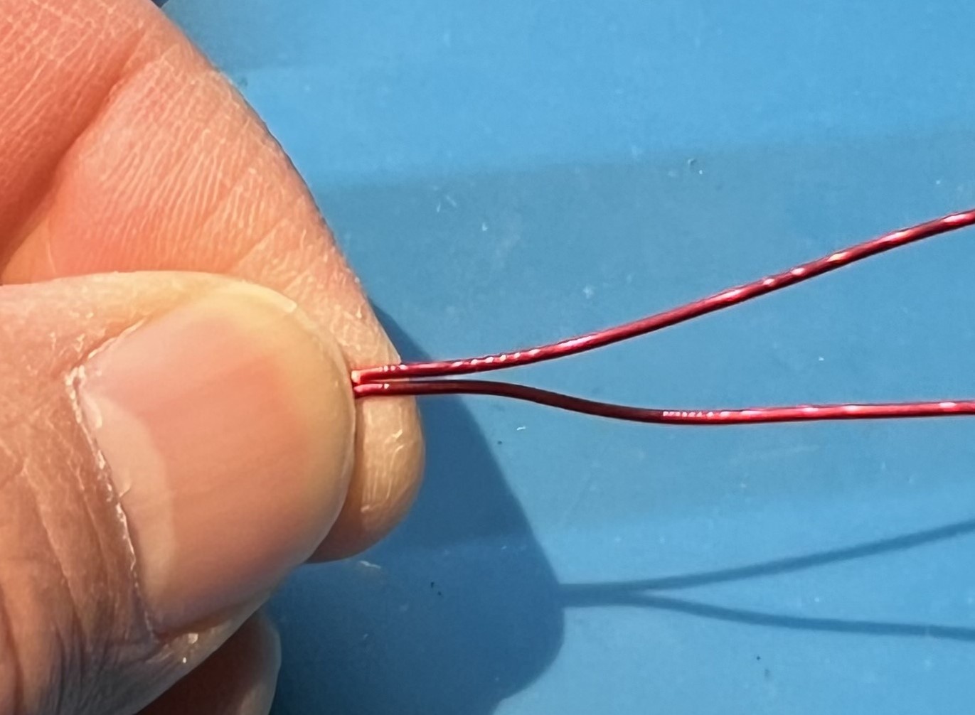
Cut your 8" wire from your length of wire.
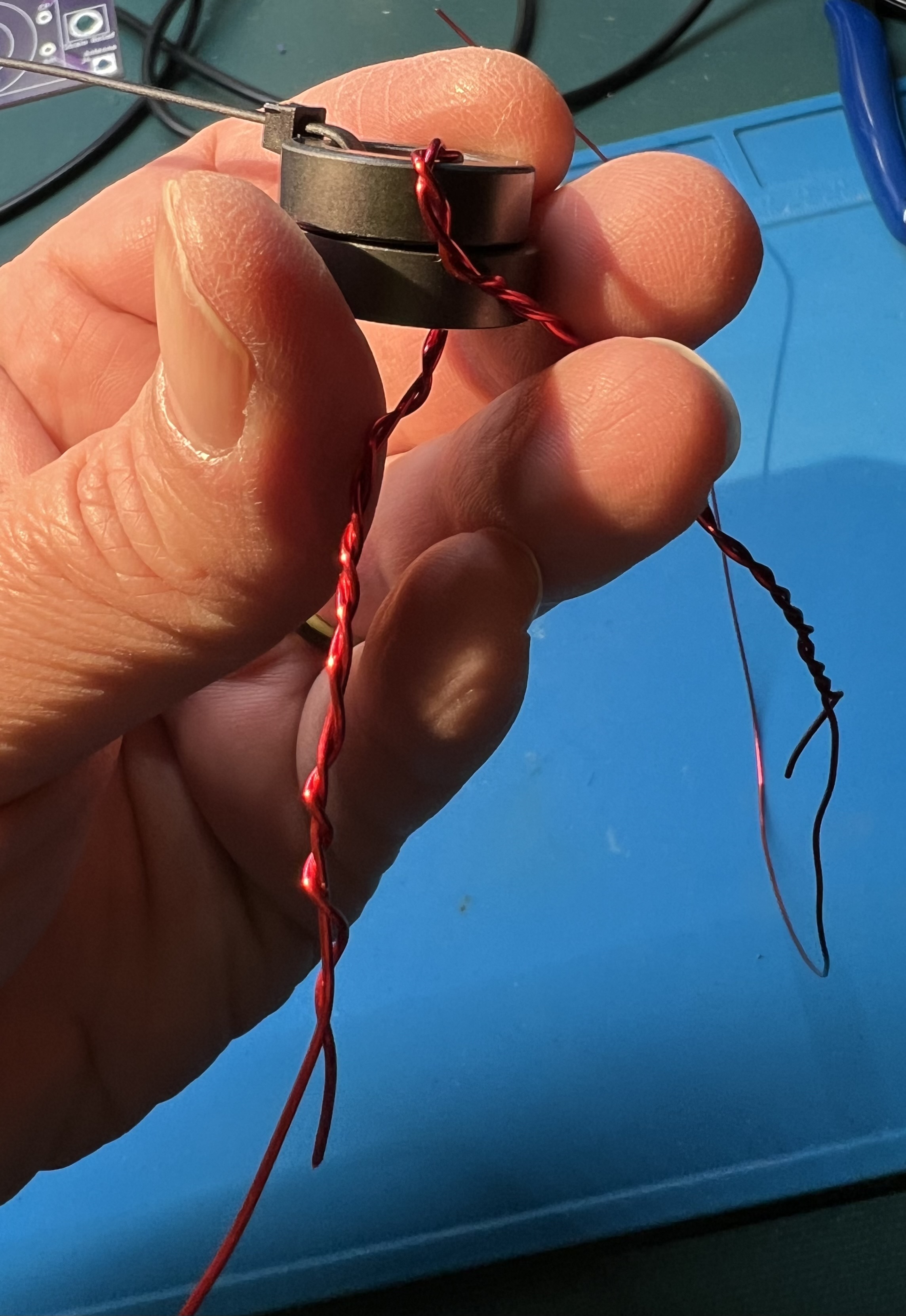
Fold them both in half to find the middle of each wire.
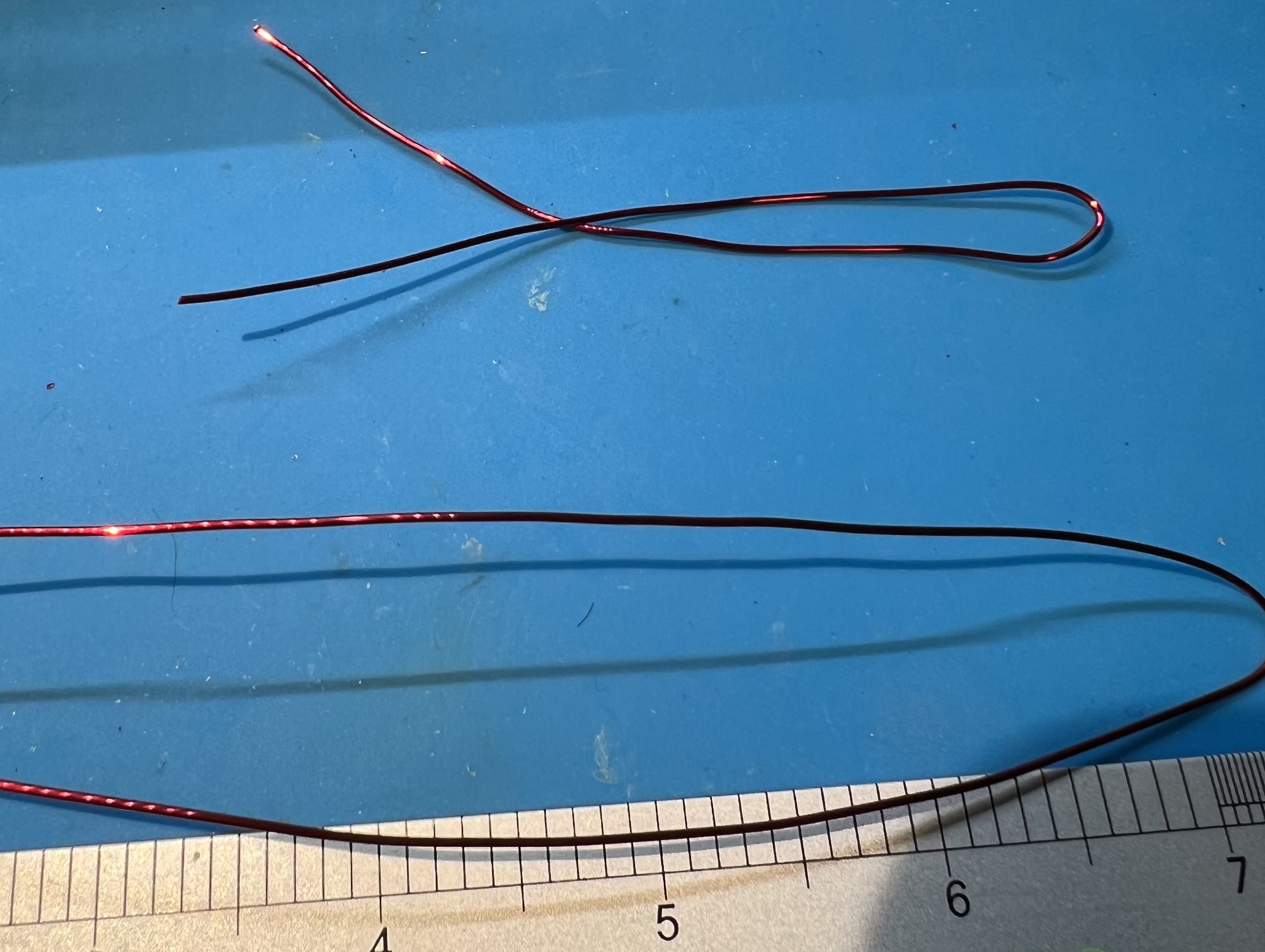
Grip the wire in the middle and twist some in each direction.
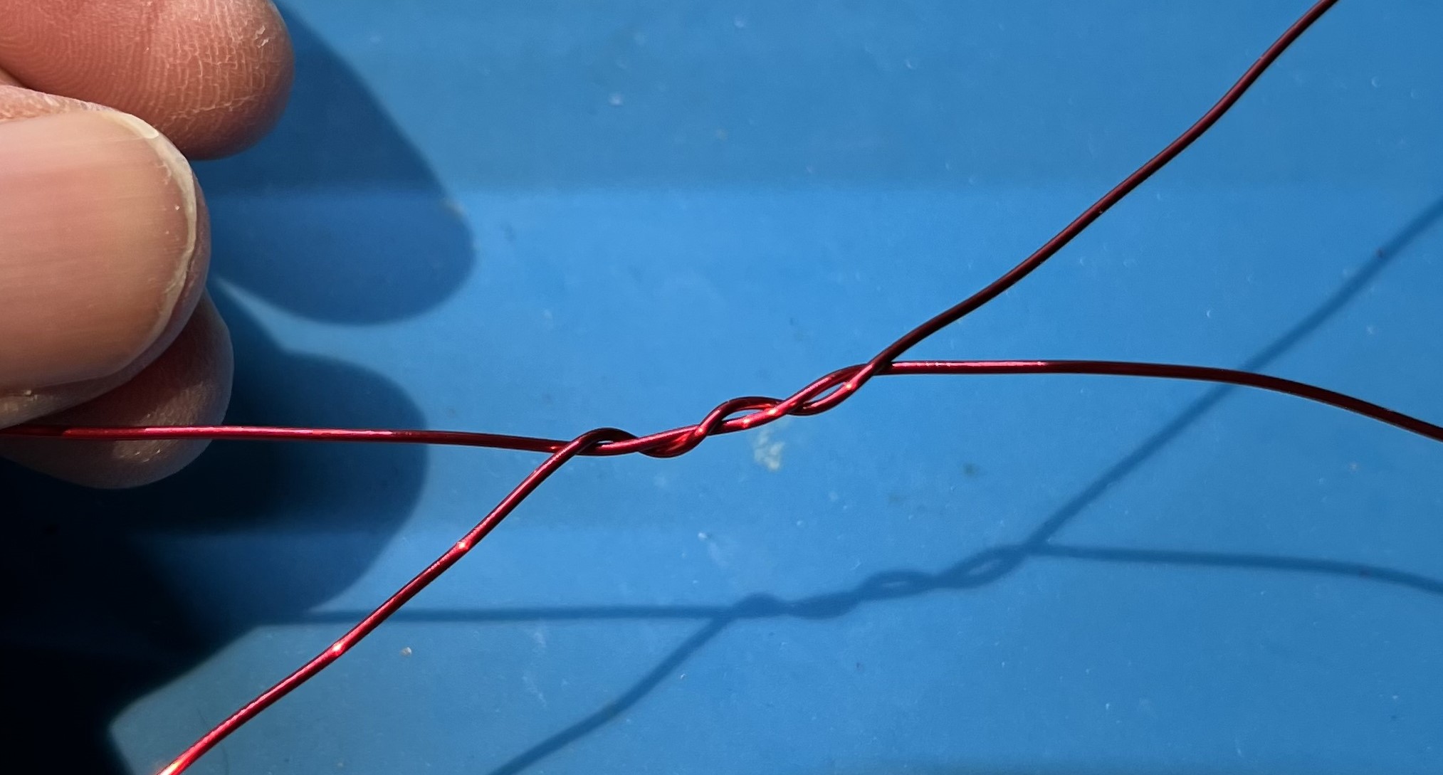
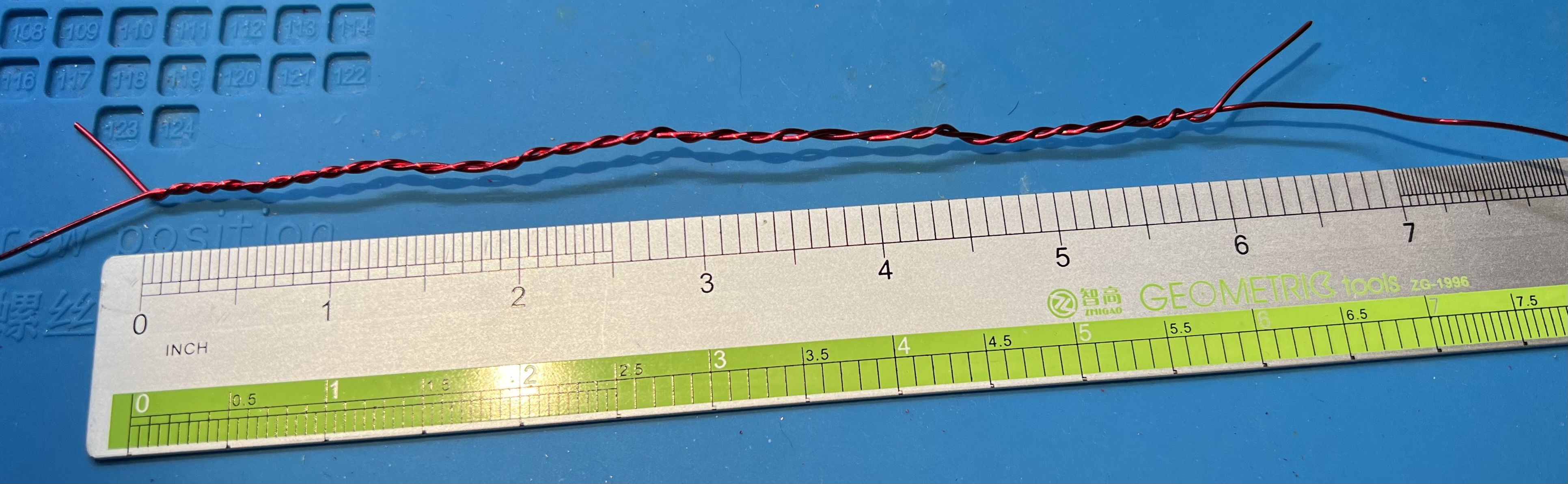
You need about 6" of twisted wire.
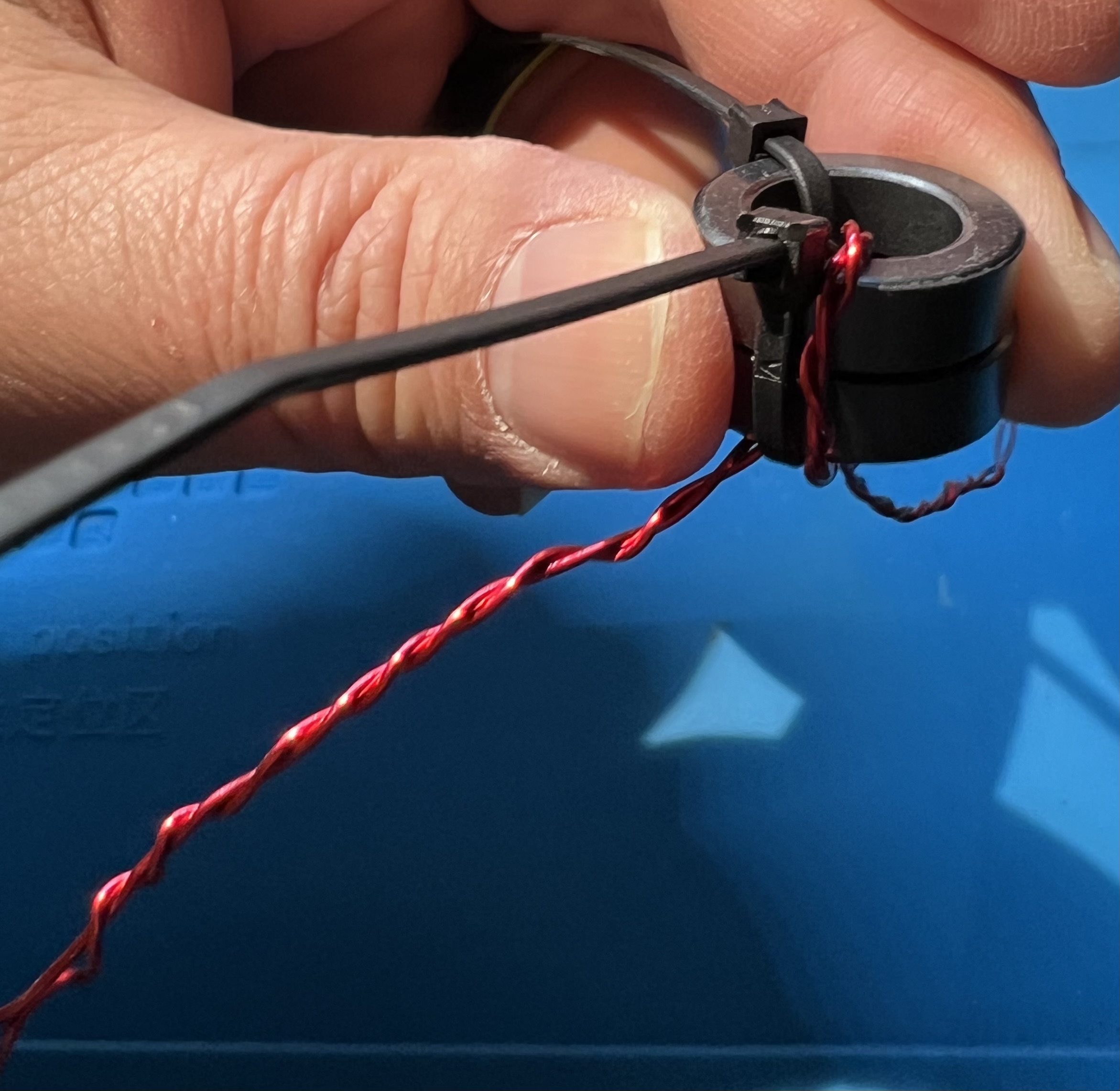
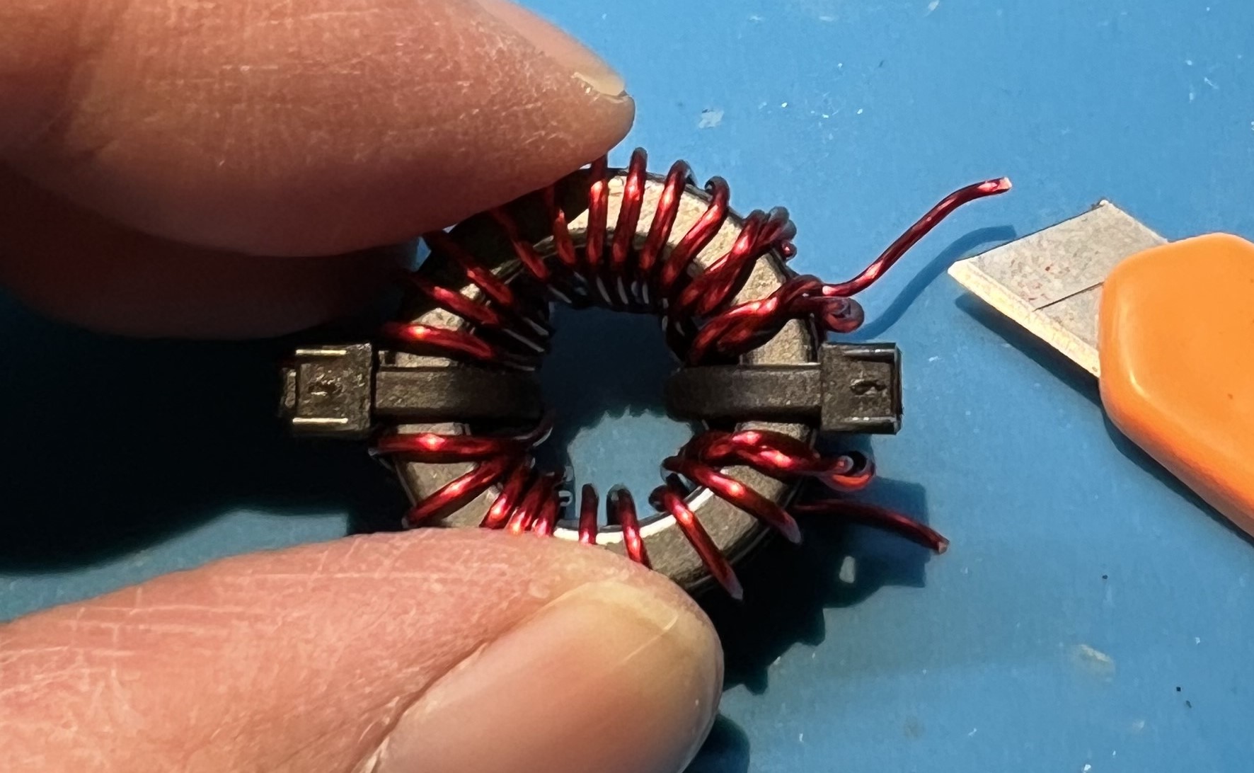
Use one of the zip ties to hold the double stacked toroids together.
Insert an end of the wire through from the top.
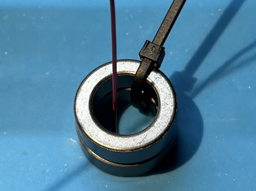
Place the first turn of the twisted wire on the toroid.
This should be in the middle of the twisted section.
Use the second zip tie to secure the first (middle) turn of the twisted wire on the toroid.
Wrap an additional turn with both wires to the left (clockwise).
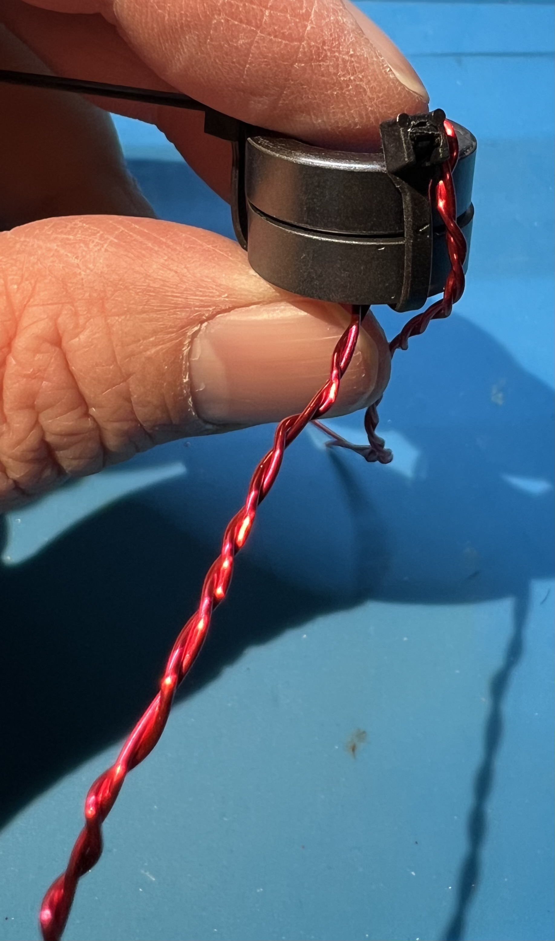
Wrap an additional turn with both wires to the right (counter-clockwise).
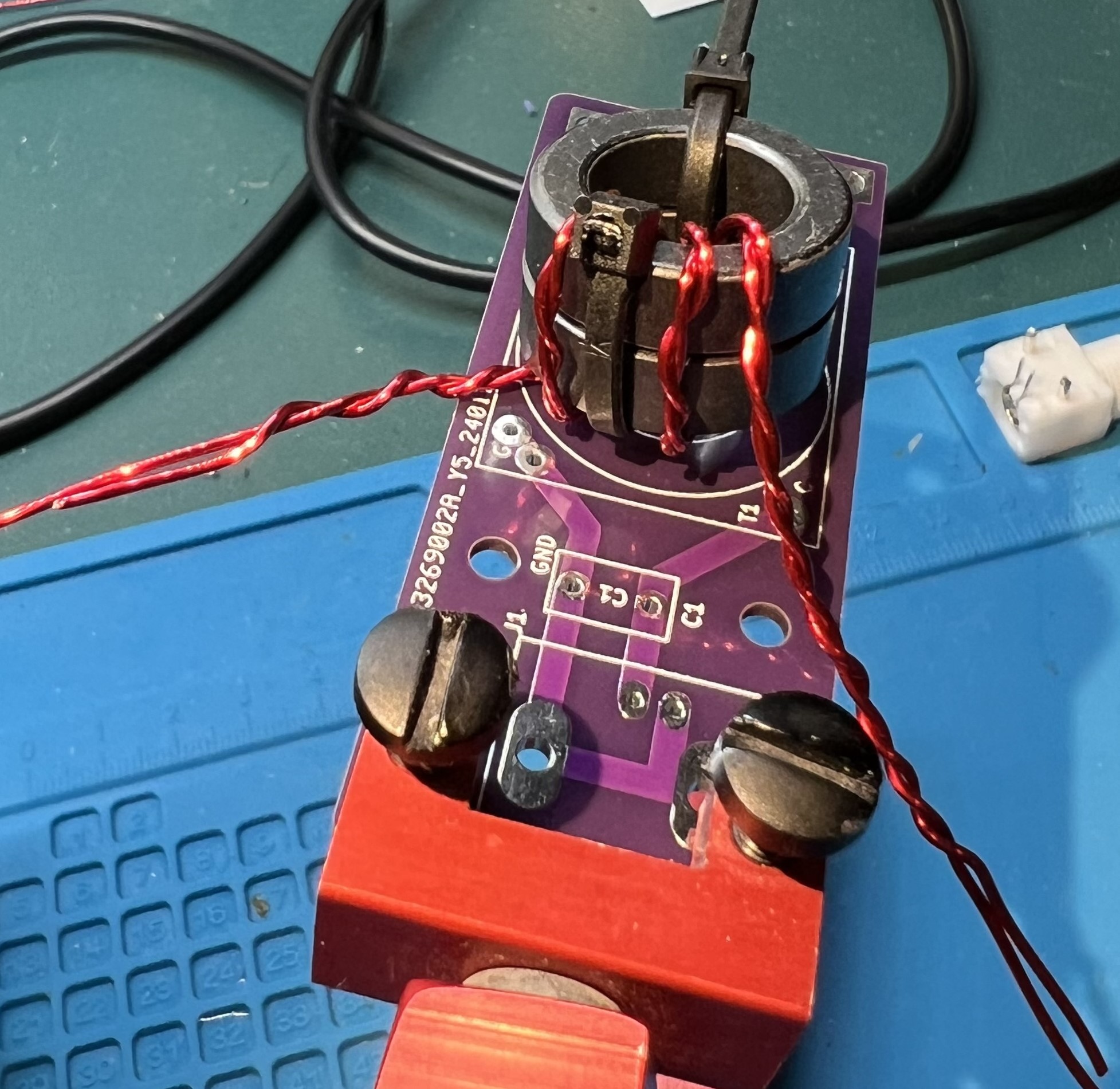
Check the twisted section against the location of the holes for the primary.
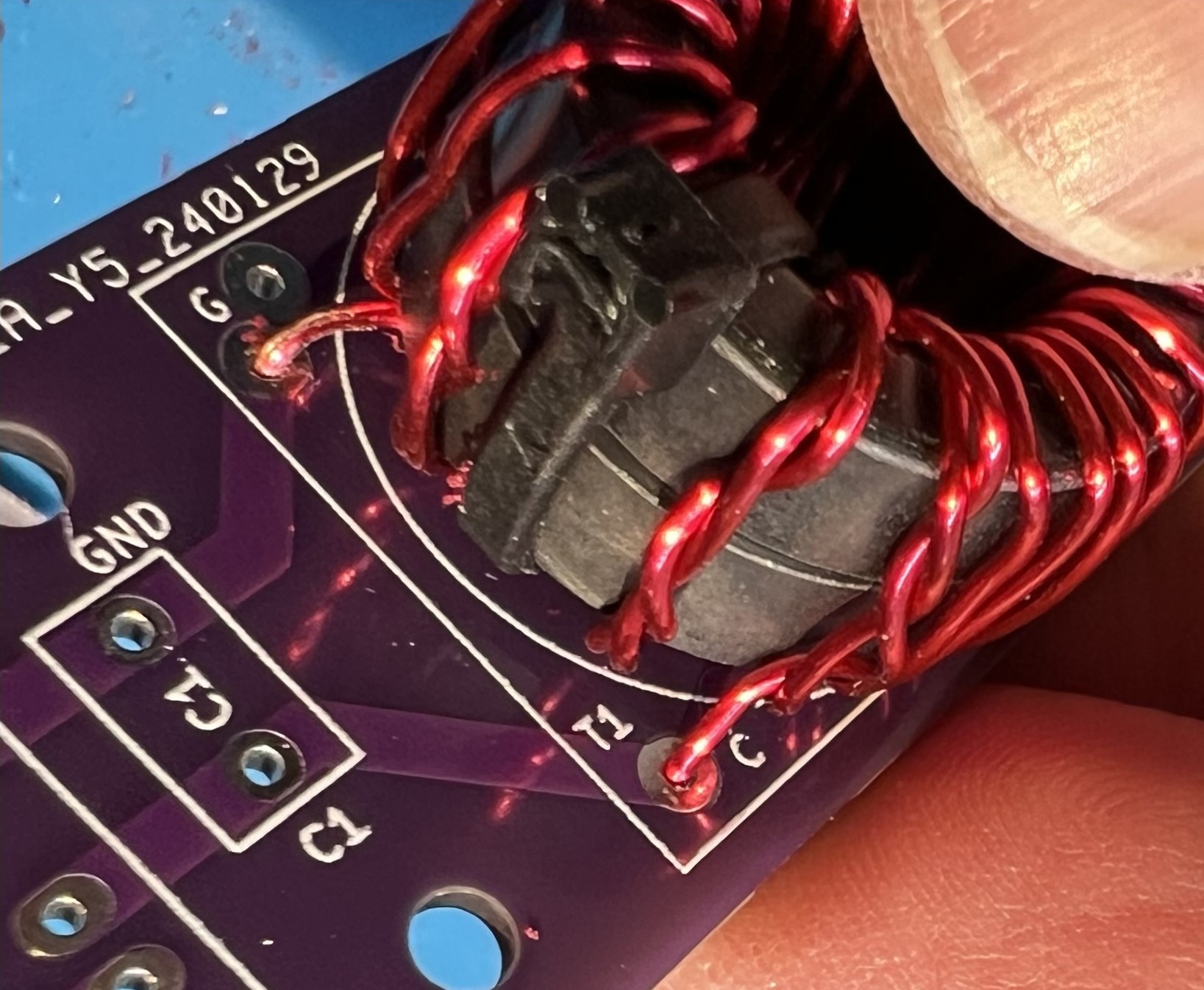
The holes are labeled G and C, inside the T1 block, near the C1 component box.
Untwist the wires as necessary so that you can cleanly reach the holes and with the other longer wire continue wrapping the secondary.
The untwisted primary that goes into the C hole and the continued counter-clockwise secondary winding.
You should count from the center double wrapped wire of the primary, counterclockwise the wire passing through the center of the toroid 11 times.
That will be the middle twisted wire and one more twisted wire to the right.
Followed by 9 more turns of single secondary wire.
Now, do the same thing but continuing clockwise.
Start from the middle winding of the twisted wires.
Count it and one more twisted to the left.
Now wind 9 more to the left.
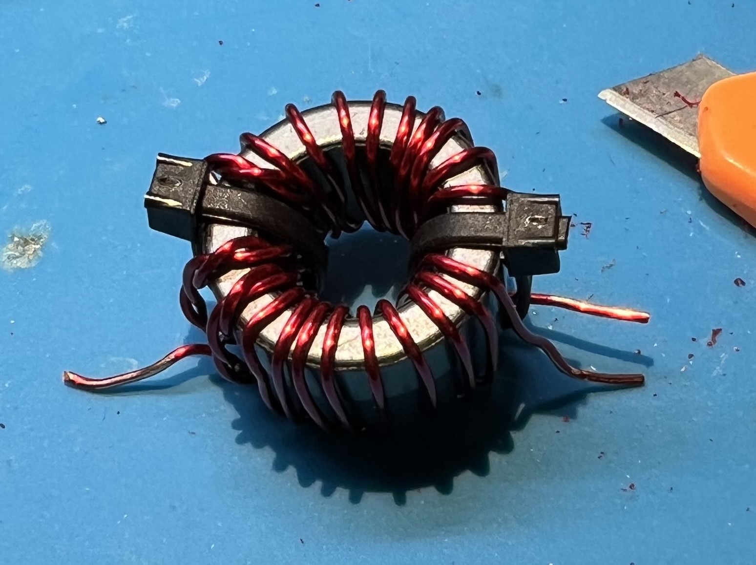
In total you will have 21 windings.
But, we counted 11 twice you protest!
Well, that’s because we counted the first winding (the middle winding) each time.
Now is a good time to give yourself a pat on the back or take a break.
Placing and soldering
Place the prepped transformer against the board.
Line up the wires against the through holes.
Verify you can get the wires in the holes.
Trim the wires, but leave some excess.
Use a utility knife to remove enamel coating from the wire where you will be soldering.
I like to use a technique of holding the blade at a 45 degree angle against the wire.
Then either work the blade against the wire, or hold the blade and pull the wire.
You will need to be very careful to not nick or damage the wire itself.
Remember to rotate the transformer so that you can scrape all around the wire where it will be soldered.
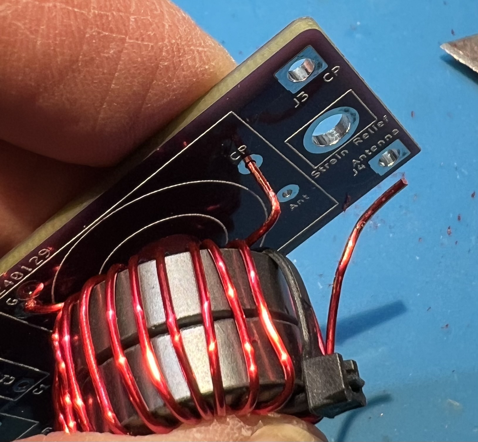
Get the primary side of the transformer into position.
Get lengths and routing checked for the secondary side of the transformer.
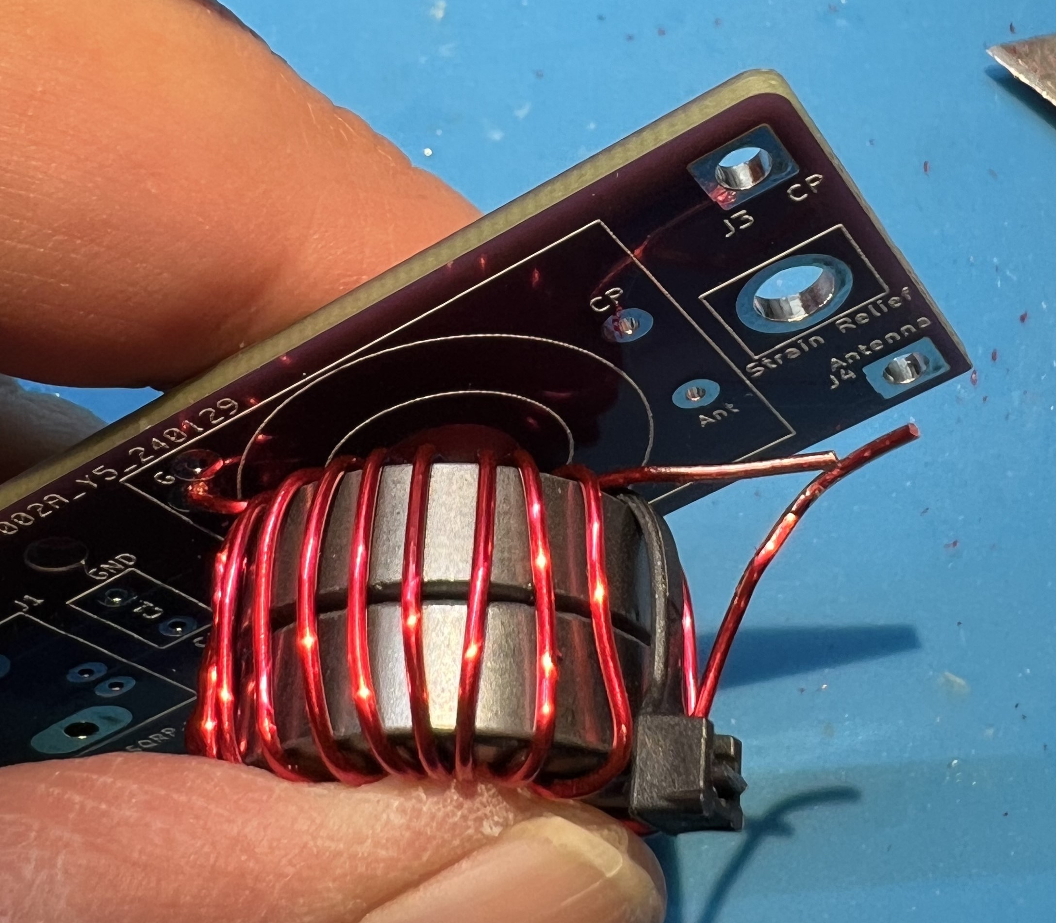
Note the bend you’ll need to get the CP end of the secondary transformer in to place.
Mini pliers can help with this.
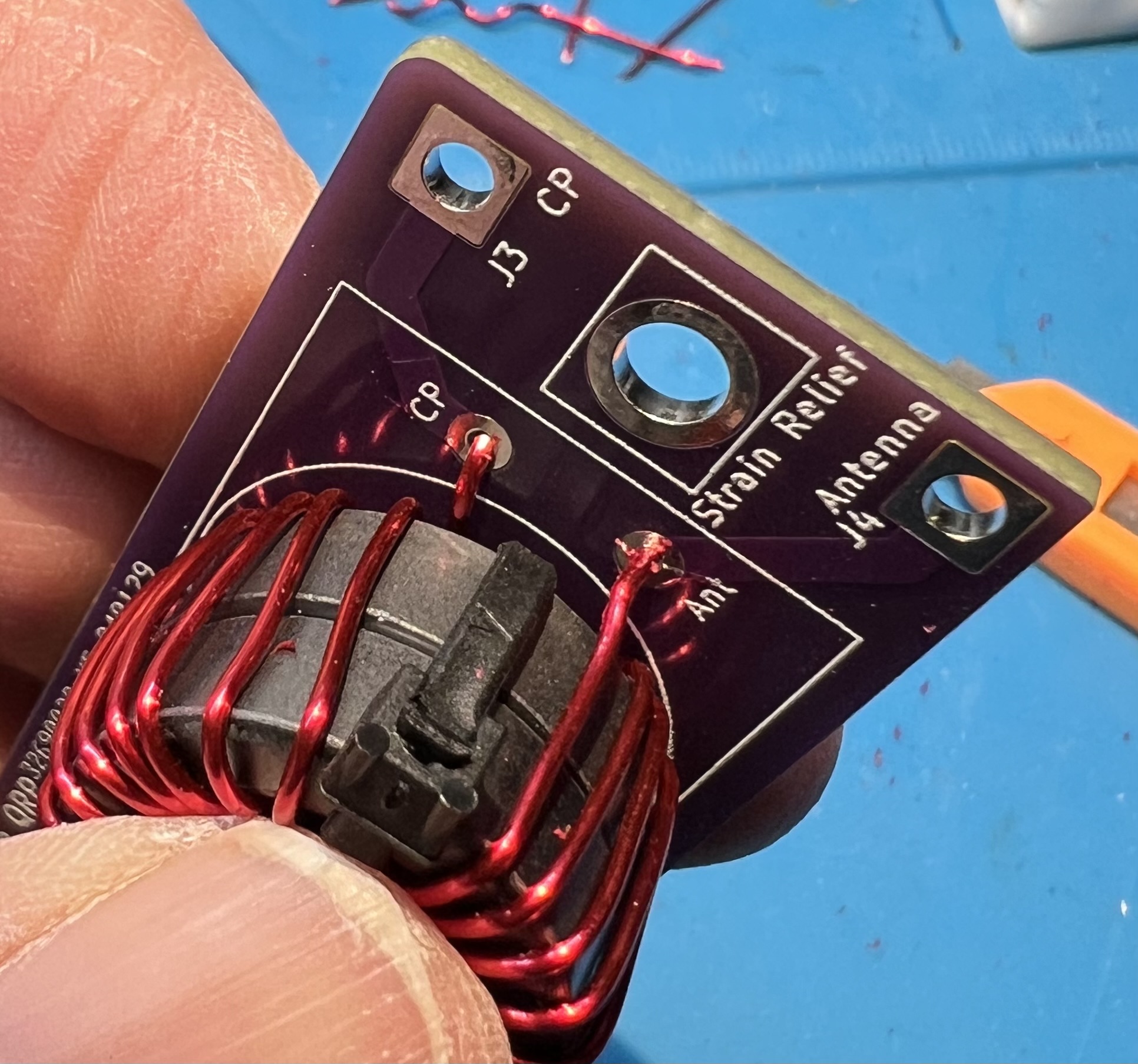
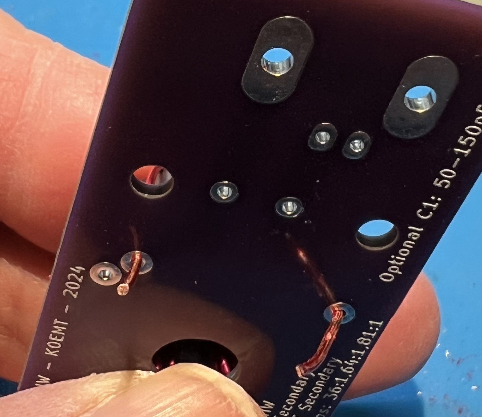
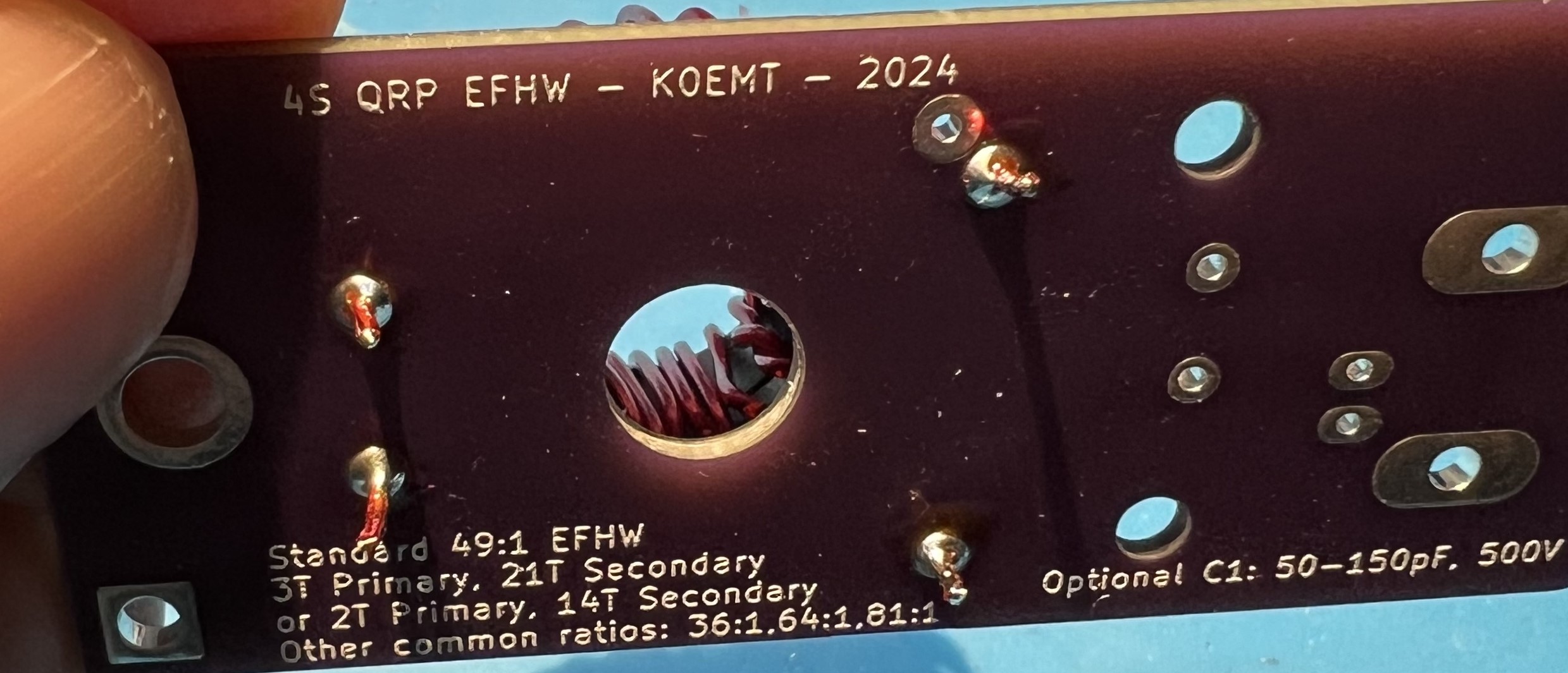
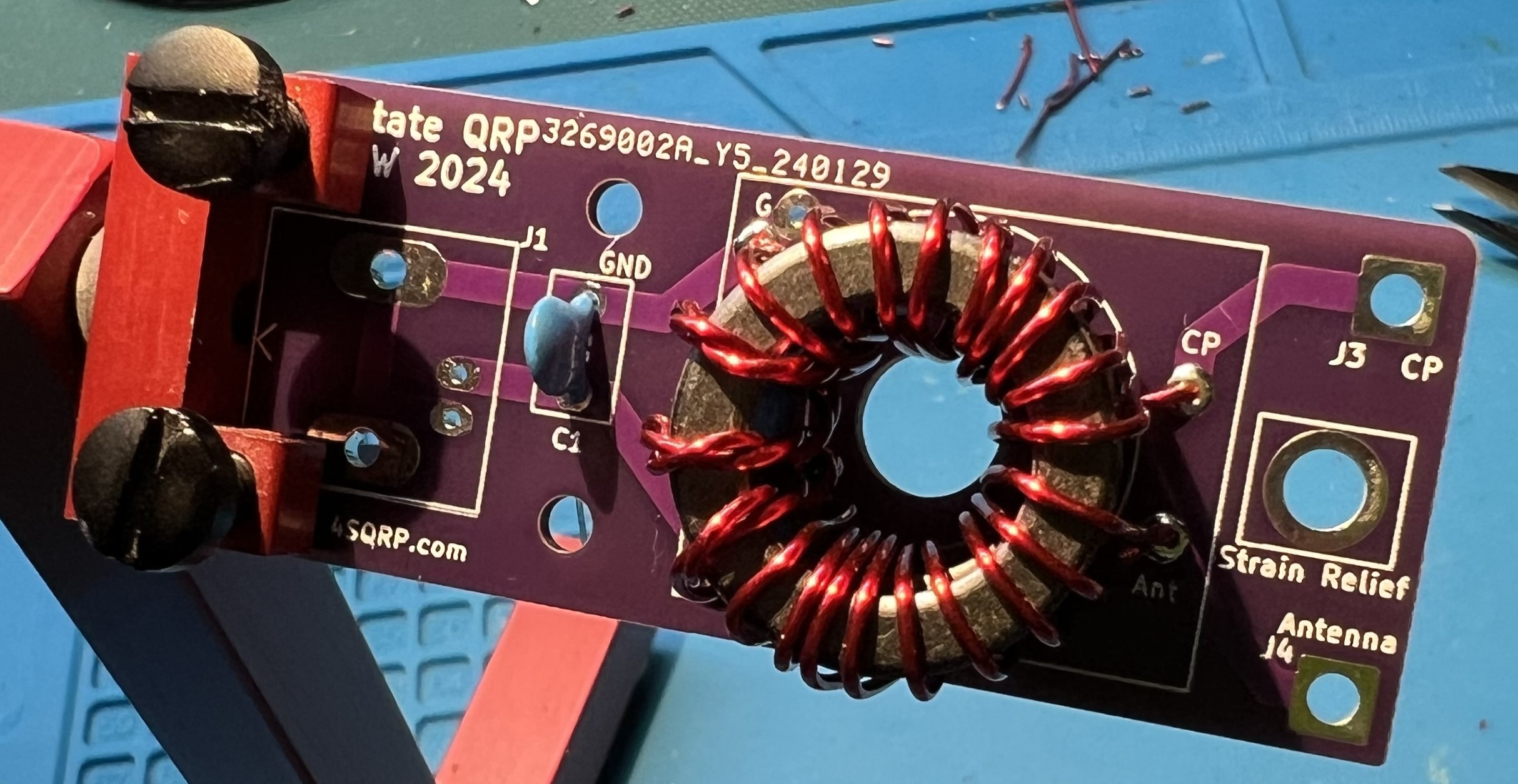
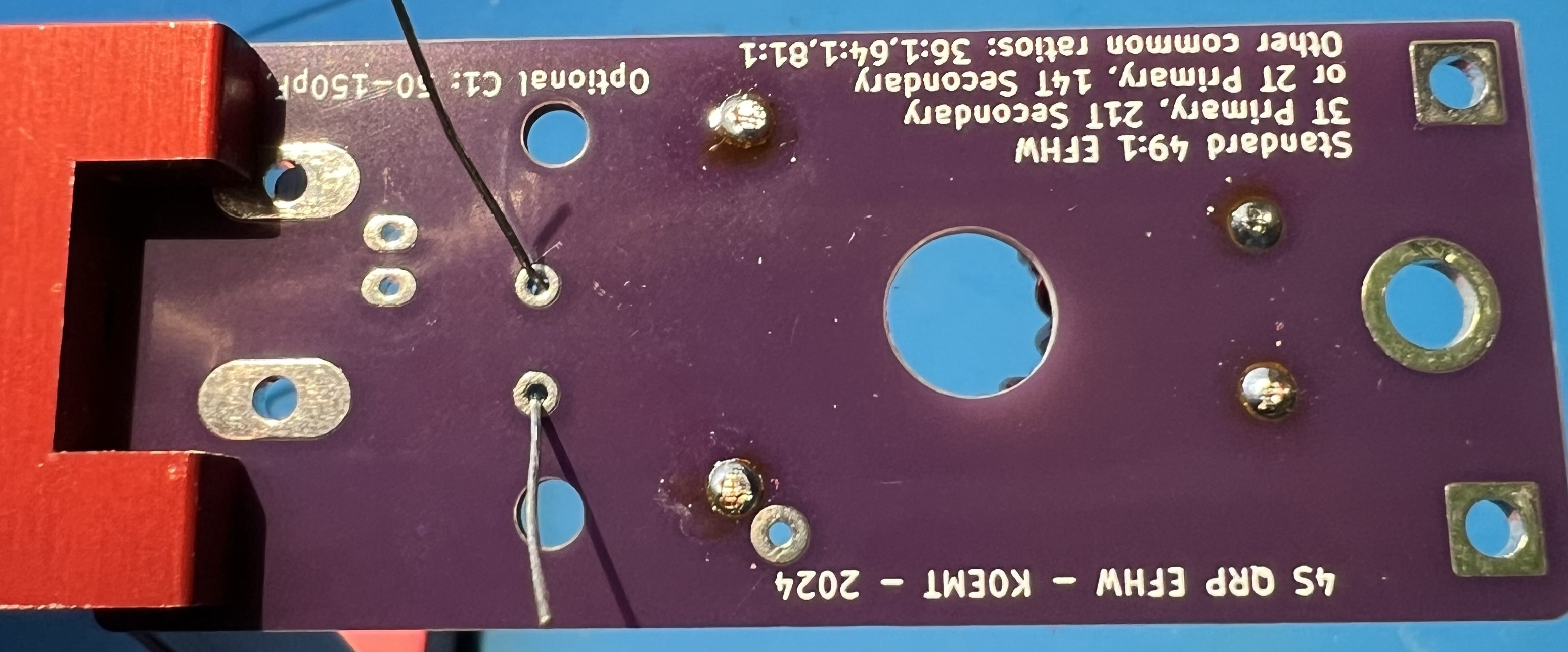
View the transformer leads from the underside of the board.
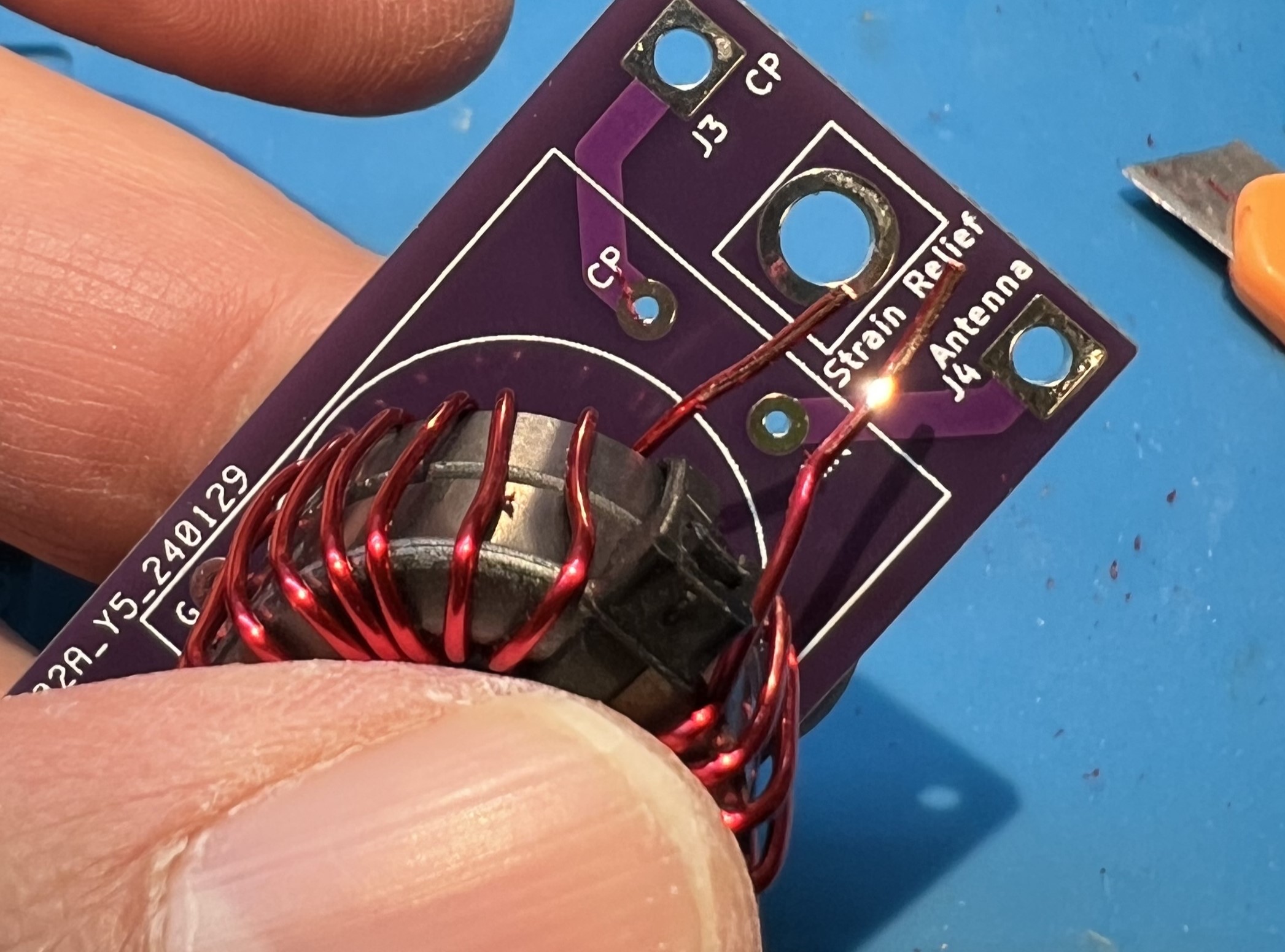
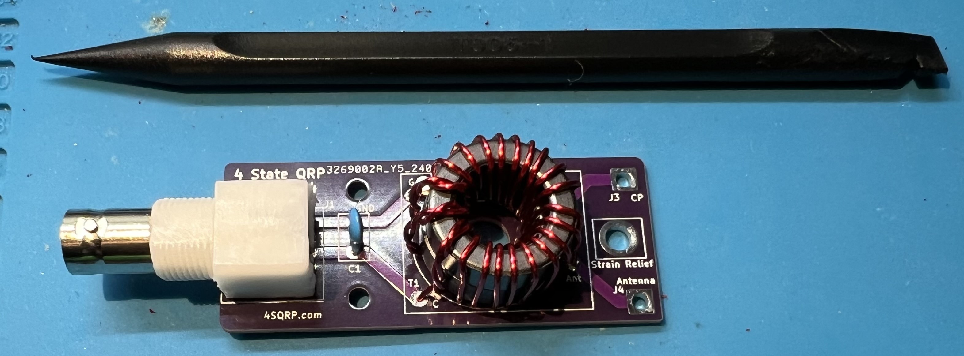
The transformer placement viewed from above and primary side.
NOTE: at this time the zip ties have been removed.
Wire leads trimmed a bit more, ready to solder.
Avoid overheating the wire and melting enamel further up into the toroid.
Note that the blue surface pictured here is a heat resistant silicone mat.
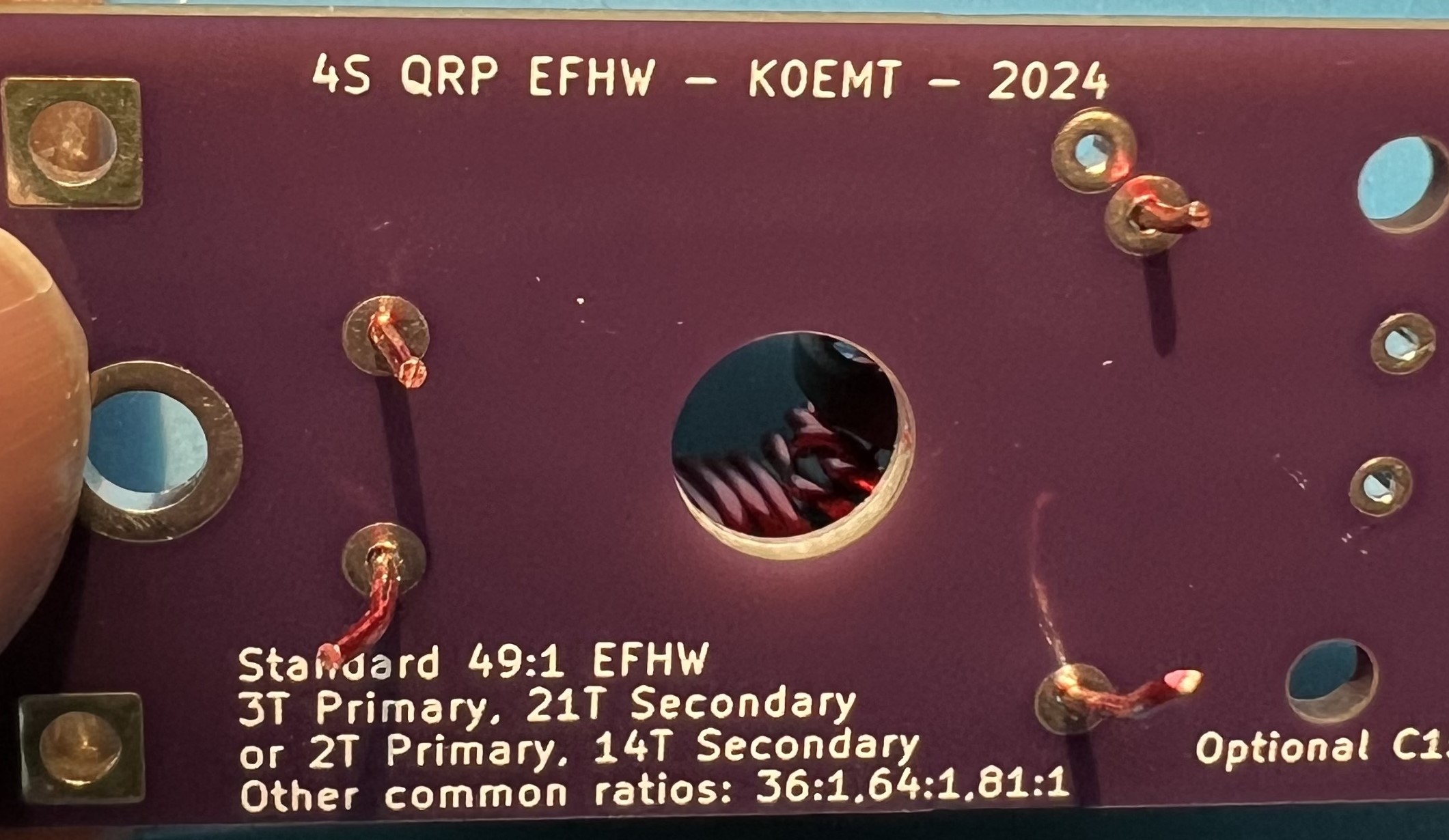
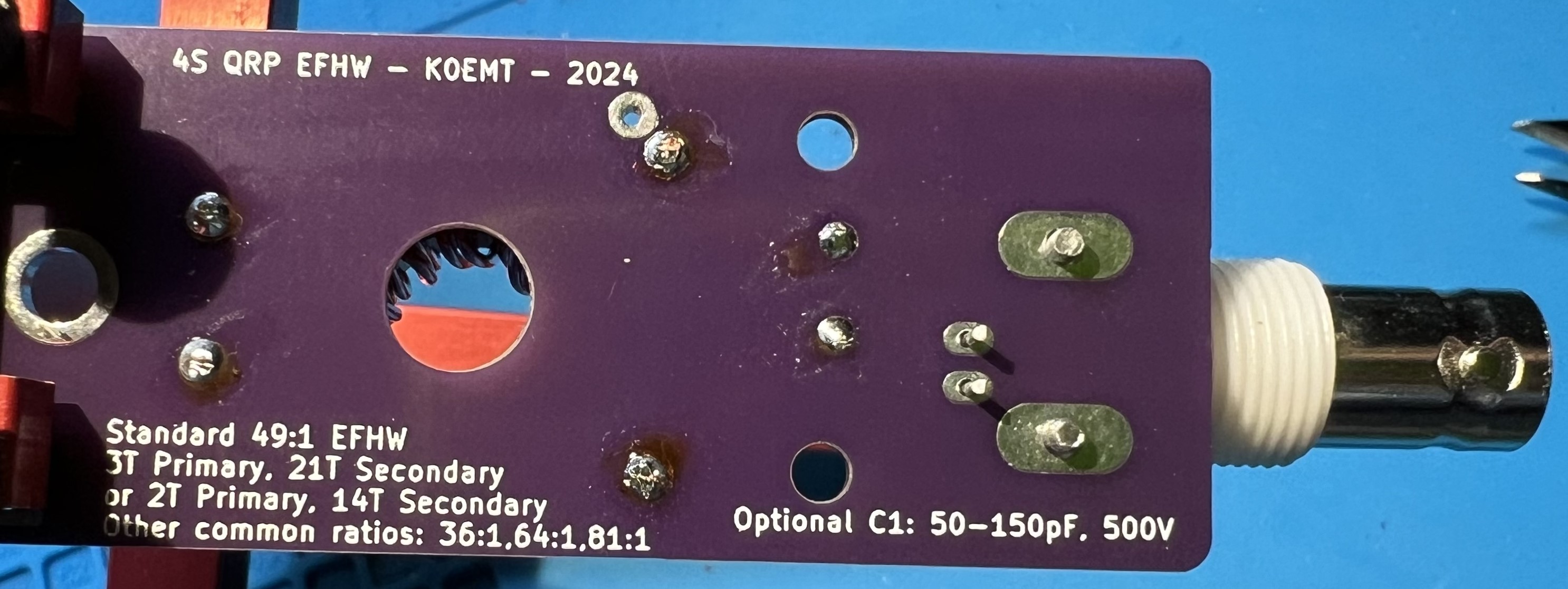
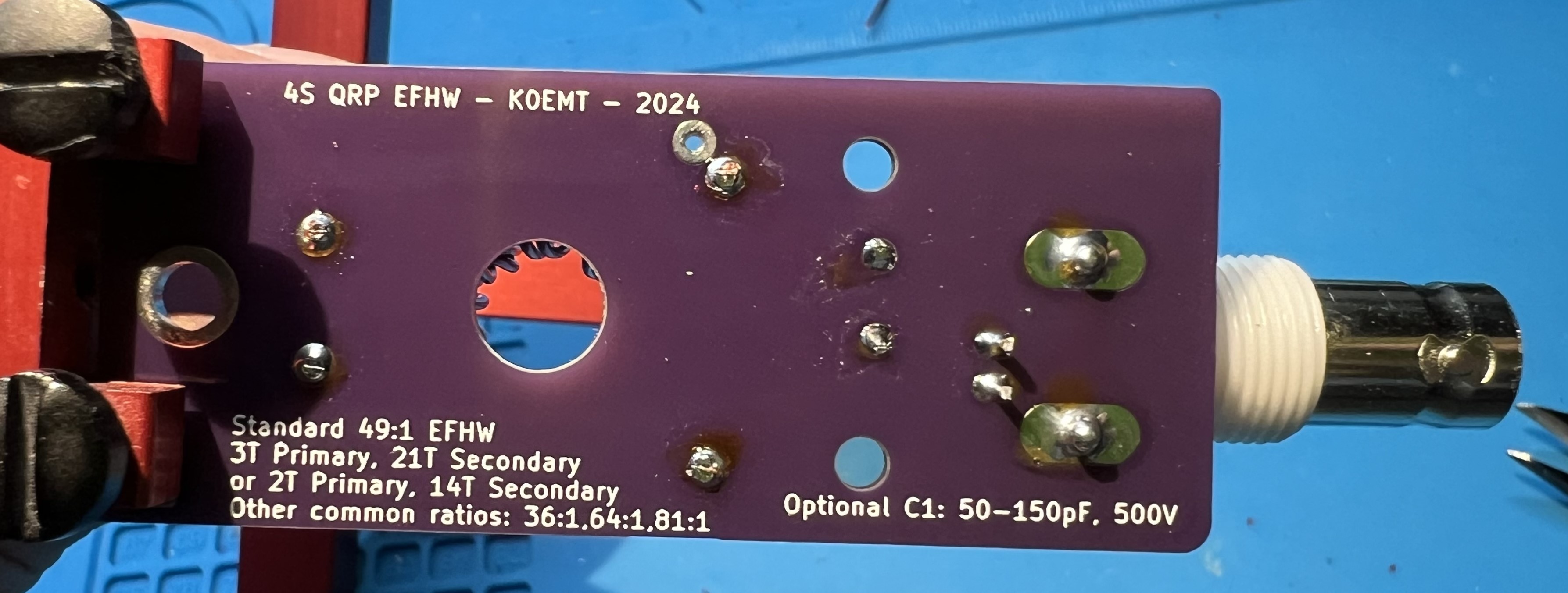
Note that the solder is covering the pad and the wire where the enamel coating was removed.
Testing
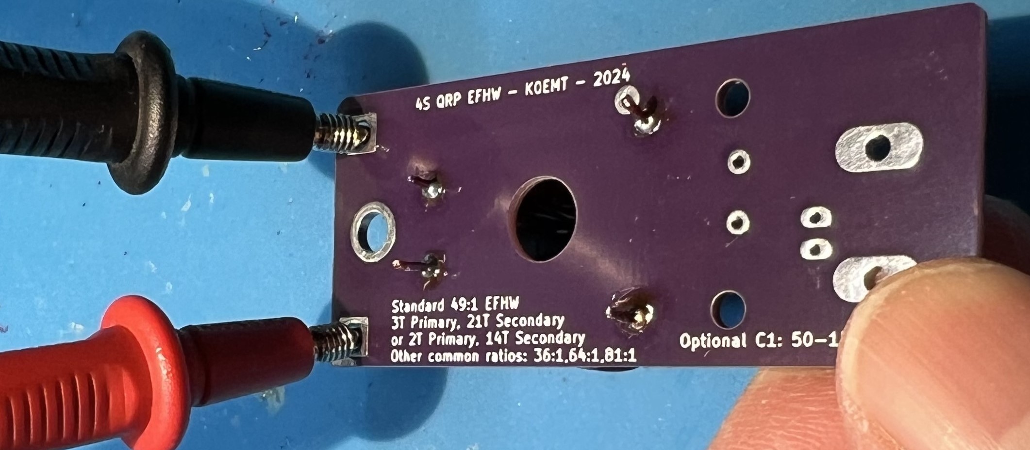
Test for good continuity on the secondary winding. Use an ohm meter to check for continuity between J3 CP and J4 Antenna on the output side.
If you don’t have continuity, that means you didn’t get the enamel off of the wire at the through holes of the secondary.
Inspect and correct wires at CP and Antenna in the transformer block.
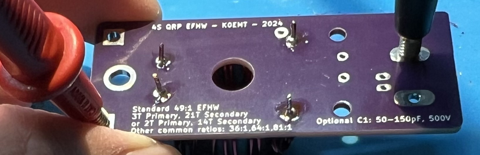
Check for continuity between the BNC mount holes and the secondary side CP and Antenna connections.
You should not have continuity here.
If you do have continuity, that means you have somehow shorted the primary and secondary wires.
You will most likely need to remove the windings and restart with new wire.
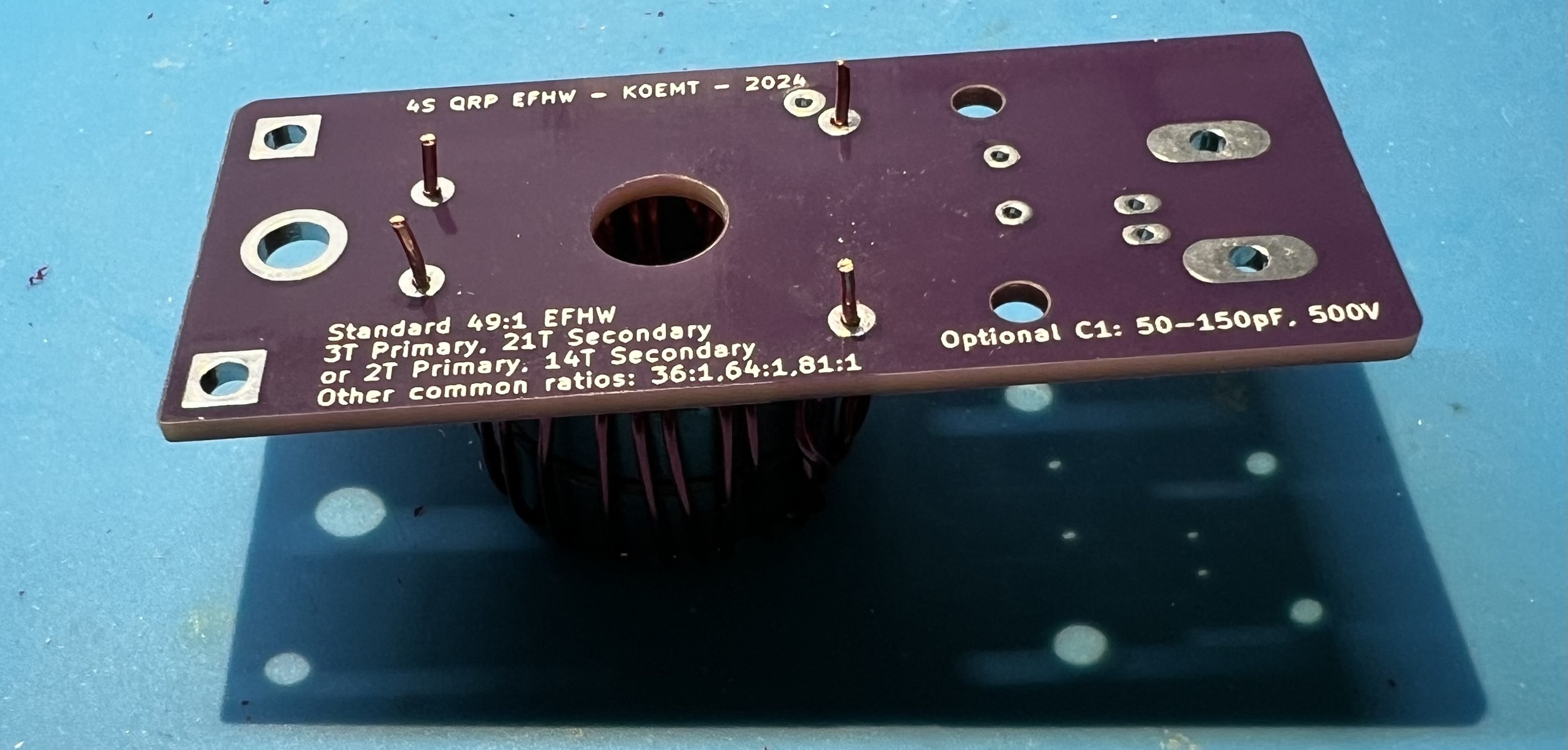
Flip the board over and test for continuity in the capacitor block C1. You should have continuity when you place your leads here. If you don’t have continuity, that means you didn’t get the enamel off of the wire at the through holes of the primary. Inspect and correct wires at G and C in the transformer block.
Wrapping up
Trim leads.
Solder the capacitor in place now.
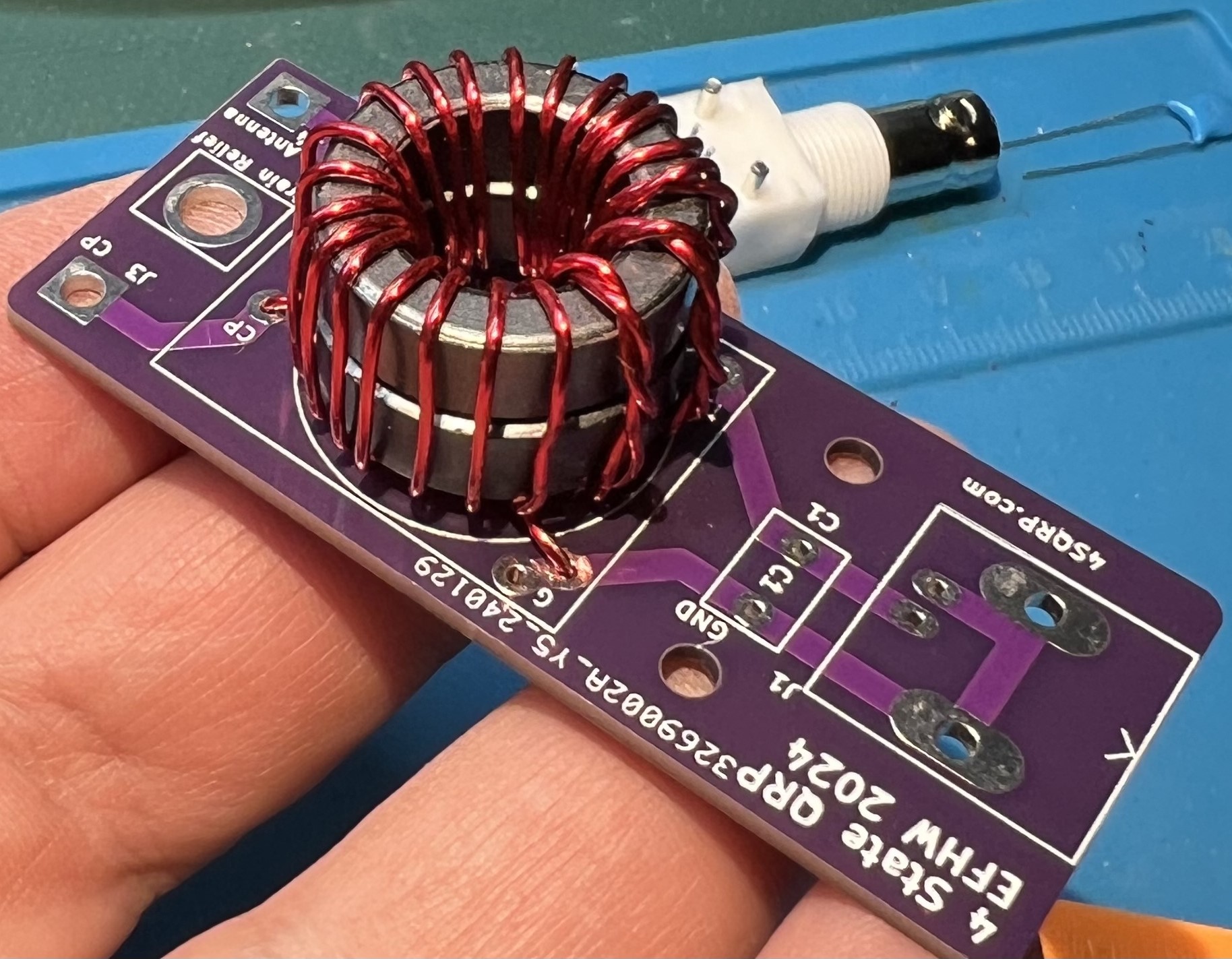
Solder the BNC in place now.
Use a spudger to spread the transformer turns both inside and around the core.
The spudger is plastic and is used to avoid damaging the wire or the enamel coating.
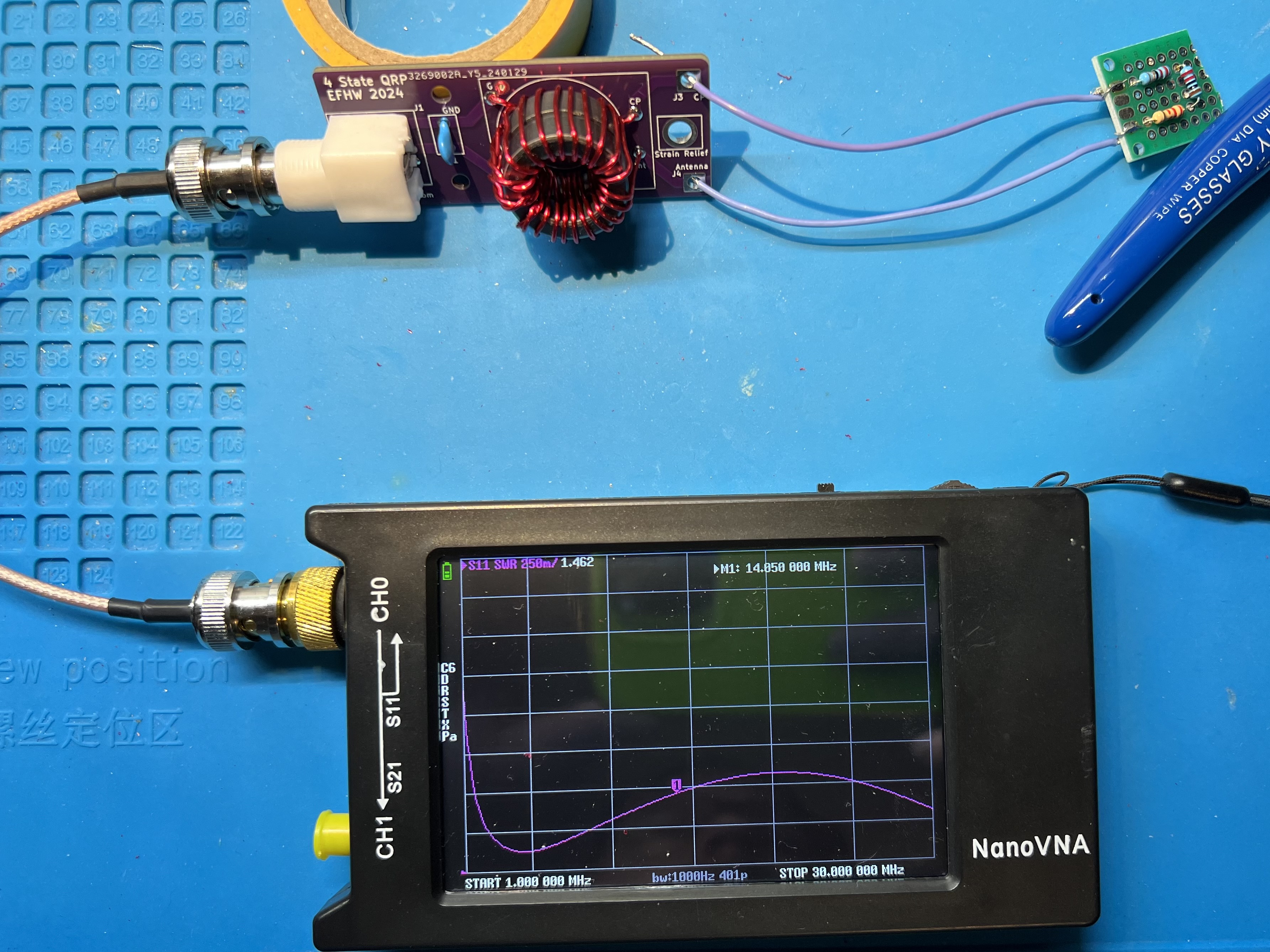
Transformer with a resistive test load and a nanoVNA showing SWR plot.