2024 EFRW Transformer
Components
- Bare PCB
- BNC connector
- Toroid T94-6
- 48" of 22AWG enamel coated wire
Tools
- flush cutters
- mini pliers
- utility knife
- ruler
- soldering iron, set to 350C
- spudger
- heat safe work surface (or board holder)
Instructions
Winding the toroid
We will construct a 12 Turn trifilar winding.
- Cut the enamel coated wire into 3 equal lengths of 16". These will be your winding wires.
- Take one length of wire, bend it in half to create a U shape.
- Hook this U shape over the toroid to start your winding.
- Wind each half of the wire around the toroid.
- Each pass of the wire through the toroid counts as 1 turn.
- You want 12 turns around the toroid with each wire.
- Be careful to not scrape off enamel coating when pulling the wire through the toroid.
- Press the wire tightly against the toroid.
- Repeat the above process for each of the two remaining wires.
- These wires should be wound between the turns of the previous wire(s).
- Do not cross the wires over each other. Each wire should have its own separate, parallel path around the toroid.
- Once all wires are wound, double-check your work. You should have 12 turns per wire, for a total of 36 turns.
Testing and soldering the toroid
Construction and testing:
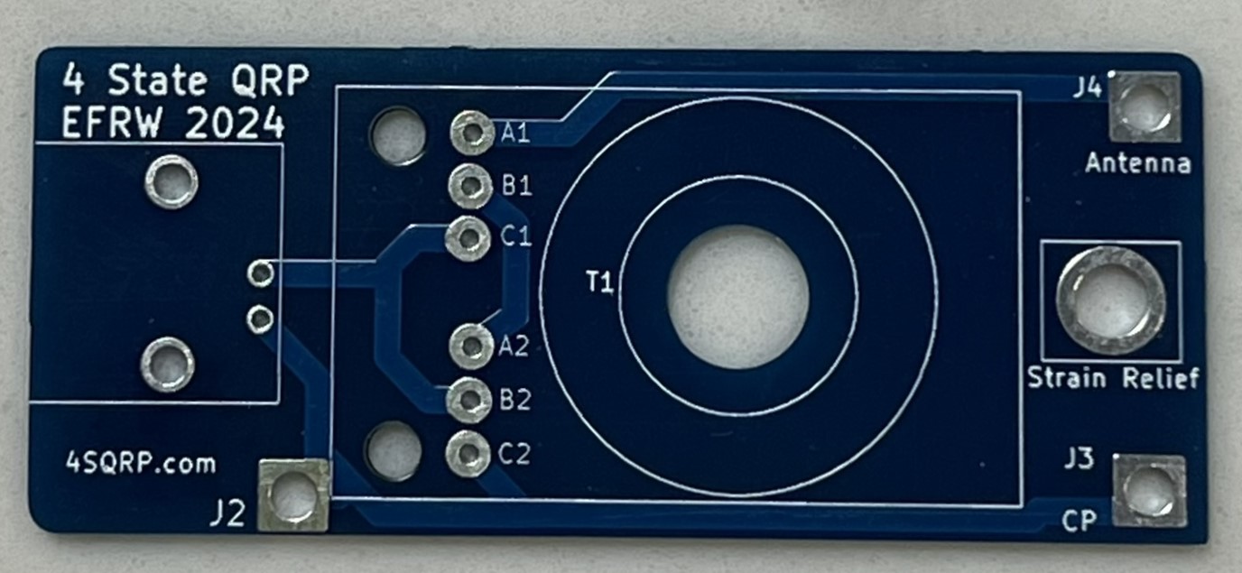
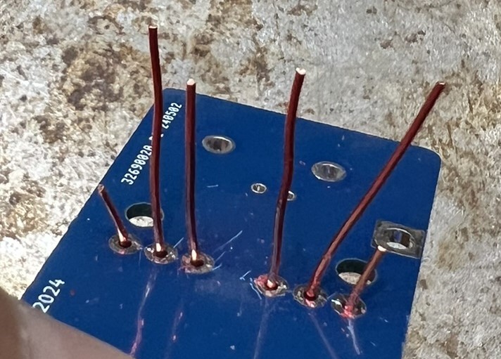
- Feed the ends of the wires through A1, B1, C1, and A2, B2, C2 on the other end. DO NOT TRIM the wires yet!
- Remove a bit of the enamel from the ends of the wire. Where the wire is NOT in contact with the through hole it is passing through.
- Use an ohm meter to check that you have continuity between A1 and A2, B1 and B2, and C1 and C2.
- Now, carefully trim the wires, and remove enamel so that the wires will contact the through holes.
- Solder connections.
- Test continuity from BNC center to J4 - Antenna.
- Test continuity from BNC ground to C1 and J3 - CP.
Note: the spudger can be used to evenly space the wire around the toroid.
BNC
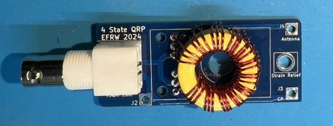
- Solder the BNC to the board.
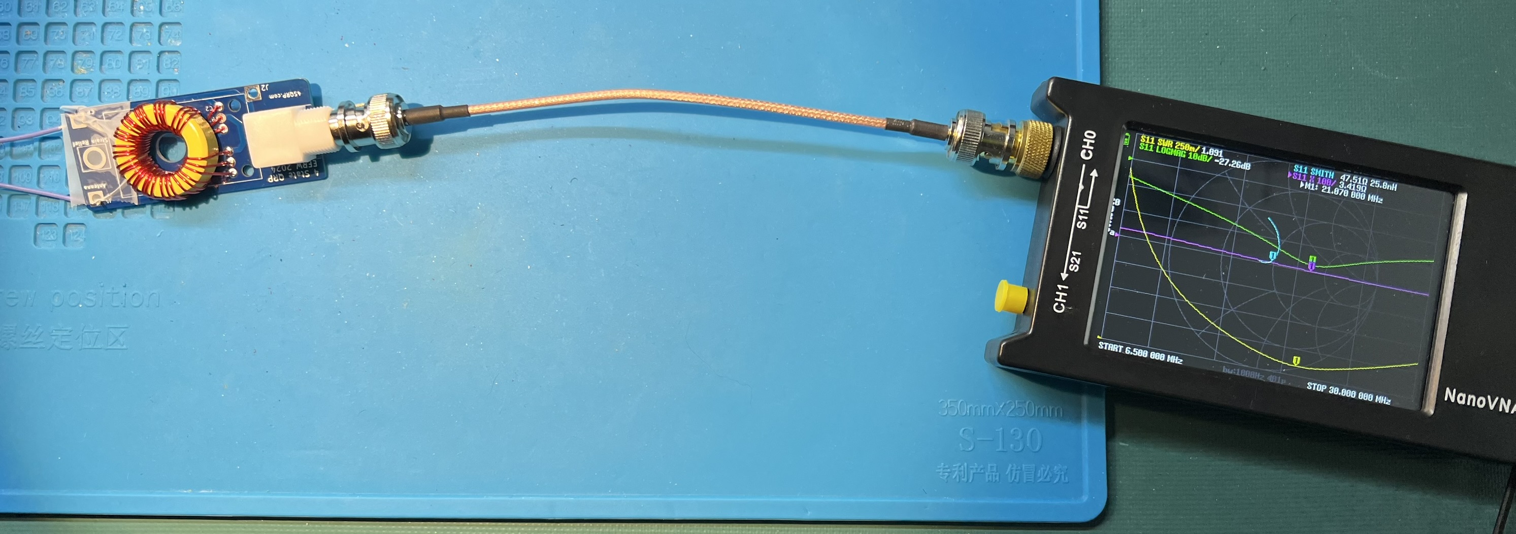
- Check the transformer with a nanoVNA and 450 Ohm resistor.