Subsections of Antenna Projects
900Mhz Antennas
| 928 5 element colinear | |
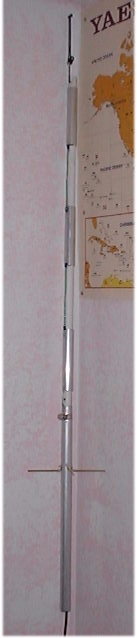 |
1" aluminum tubing was used for the large sections. 12 gauge stranded copper wire with ring connectors for the small wire sections. The ground plane wires are from brass rod. Ring connectors were soldered on to the brass rod. The rods were riveted to the base section of tubing. All stranded wires were riveted to the larger aluminum tubing. The coax used was Radiall-Larsen Dual shield RG-58. Peformance is much better than the three quarter wave below. A station that had quite a bit of QSB on them with the 3/4 wave was Q5 with this antenna. With the SMA3 they could not be heard and they couldn't hear me either.
I really need to go back and rebuild this antenna. After revisiting Ross's site below, I realized that my first element is improperly built. I should be feeding the first fat element in the center. I also did not utilize the 75ohm quarter wave match that he does.
I built a similar 3 element colinear for VHF. I tried the techinque of feeding it through the bottom section to act as a decoupler trick and it doesn't appear to work all that great. I'm going to try it out again with a 75ohm quarter wave match. This site was the inspiration for this antenna. I just sized things for 928Mhz. |
| 928 3/4 wave | |
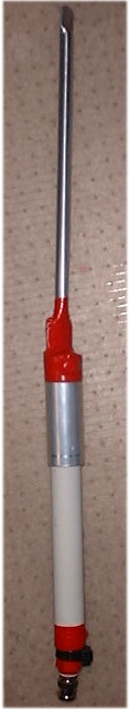 |
This antenna was built with all scrap box parts. The top piece of aluminum tube was left over from an antenna trimming/conversion project. The bottom piece of tube was from scrap that was cut off of another antenna. The RG-58 a/u with molded BNC was another piece of scrap. As well as the PVC tub that serves as a support. The ends of the coax had ring connectors soldered on them. Both piece of aluminum tubing were drilled through the pvc support. Then the coax ends were connected to the aluminum tubing with aluminum rivets. (The tape is added for waterproofing and aesthetics.) It performs better than the Comet SMA 3 it replaces. |
Base Loaded 160m Half-sloper antenna
I wanted to have a resonant antenna on 160M so this is what I came up with.
Materials
- 3in PVC tube
- PVC Caps
- Mirror Mount Bracket
- Spring
- ~66ft of Flex-weave wire
- 12awg solid copper wire
- Spade type connectors
- PVC cement
- Miscellaneous hardware
Construction is pretty straight forward
- Drill end caps for 3/8-24 hardware
- Ring connector on end of wire that was fed through PVC tube for cap.
- wrap wire around coil form. Every so often place a tap (spade connector). Closely wind wire and wide space taps for big jumps in inductance. Closely tap wire and increase space on winding for small jumps in inductance.
- finish off wire with ring connector and assemble last end connector.
- Drill very small “breather” hole in one end cap
- Put female connectors on a length of wire that will be your jumper.
Notes
- I used this on the mobile with a small mast and 56in whip for 80m.
- Sometimes when I’m really motivated I will solder all taps
- coil is wrapped in tape to keep it from shifting.
- spacing between wire affects amount of inductance
- spring on end cap was used to provide some give for wire
- 1:1 VSWR at 1.9Mhz. 9:1 at both ends of the band
- If you can find end caps that are squared off and flat instead of rounded you will make things easier on yourself.
F-150 Mobile QTH
 |
k0emt's 6m/2m whipI used a completely threaded 3/8"x24 TPI bolt with an Allen style head and a lock washer for mounting the cobalt steel heavy duty spring to the mount. Next is a lock washer and a medium duty stainless steel spring. Then a 3/8" x 3" extender topped with a barrel connector with locking nut. A whip adapter with stainless steel whip tops it all off. The radios in my truck are mounted on a "Shelf-it" brand over head shelf. I went with this brand because the fabric covering is actually fabric particles that are blown on to an adhesive coated aluminum shelf. (That way you don't rip all of the shelf material off when you are drilling holes!) |
 |
 |
Field Expedient dipole for 80m
SummaryThis is my 80M "field expedient" antenna. I primarily use this as a NVIS antenna with my FT-817 QRP rig.Materials:
Construction:
Notes
WA2ZKD suggested the following (edited):
Variations
Reports from Builders
|
|
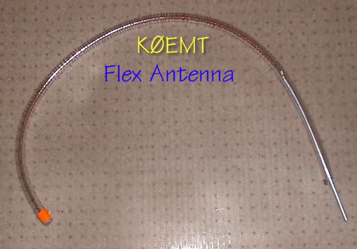
Flex Antenna
Numerous people on several yahoogroups, of which I am a member,
have commented about the need for a flexible HF antenna.
This is a prototype antenna I built up from material on hand.
- Materials
- 3/8" outer diameter Vinyl tubing
- aluminum grounding wire
- copper wire
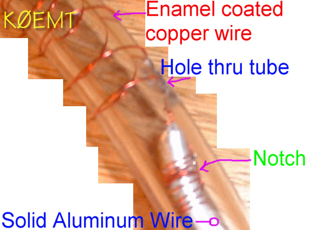
- Construction
- Cut a 6" length of aluminum wire
- Cut a hole big enough for the wire to pass through in the tubing. It should be about 4" from the end.
- Using your cutters put a notch in aluminum wire very near the end.
- Tie your copper wire to the aluminum wire. It will slip up into the notch.
- Solder the wire to keep it from slipping.
- Feed the aluminum wire through the hole you cut.
- Wrap the vinyl tube with the copper wire.
You may want to insert a rod of some sort into the tube to make it easier to wind the wire. - Secure the end of the copper wire with tape.
- Trim Vinyl tubing and aluminum wire to fit into appropriate antenna base. (I suggest 3/8" x 24TPI whip tip adapter.)
- Evaluate on antenna analyzer
- Have fun!
The antenna shown has approximately 20" of tubing.
The analyzer says it is resonant on 6M and 70cm.
On the air tests with the Yaesu FT-817 show this to be true
in operating as well.
Variation: use a section of 3/8" x 24TPI bolt instead of the aluminum wire. Warm the vinyl so you can work the bolt head into the tubing. Use a ring connector on the wire at the bolt end. Tape the wire to the tubing around the bolt head to help secure everything.
HF Receive Antenna
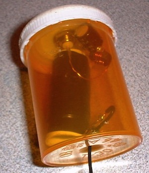
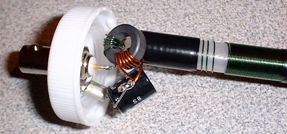
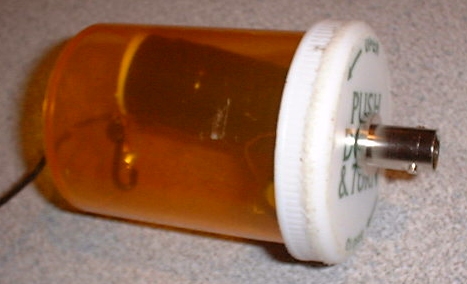
If you are only using the stock antenna that came with your SWL radio, Yaesu VX-7 or Kenwood TH-F6/TH-F7 you are missing out on a lot. This page describes a couple of parts box medicine bottle antennas that you can build. Specific values are not that important. Especially for receive only use.
In one example the coil was wound on 3/8" plastic tubing. In the big bottle example the coil was wound on ~1/2" plastic tubing.
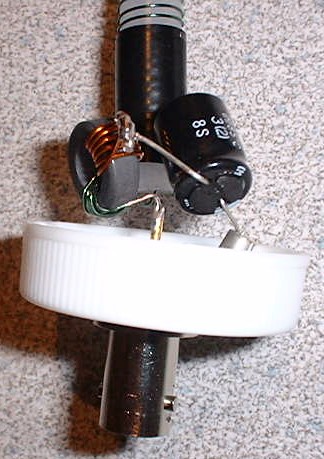
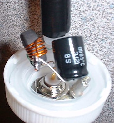
The ground side of the capacitor is soldered to the ground of the BNC connector. The positive side of the capacitor takes 5 turns around the toroid and is soldered back to itself. The center pin of the BNC connector takes 5 turns around the toroid and then continues on to the wire wound inductor. From there the antenna continues with an attached piece of wire.
Toroid, capacitor and inductor specifics are not critical as this is intended primarily as a receive antenna. You can check your resonant frequency with a tool like the MFJ-269. This simple antenna will greatly increase your enjoyment of HF SWL with your TH-F6a.
Give this simple parts box antenna and matching unit a try and you'll be surprised. I'm only using about 6Ft of wire after the inductor. For the larger coils I used a plastic form and ~22AWG magnet wire. For the smaller coil I used a piece of tubing used on water systems with very fine magnet wire. Materials and values are NOT critical for the most part. The Important thing is to have fun!
Frequently Asked Questions
- What diameter should be the of the wire winding on the core
of a plastic tube?
22 awg the inductor. I believe I used larger for the toroid. This is enamel coated wire. - On the steps which wire has to be wound on the first core
inductor, for how long and what section of the pipe has to be the
best on the tube diameter wound wire will also be useful to know the
total length of the wire?
The center + side of coax takes 5 turns around the core and continues on to the inductor. The ground - side of the coax goes to the capacitor. From the capacitor it takes 5 turns around the core and folds back on itself. The picture at http://www.dbbear.com/k0emt/projant/hf_rcv/mb_core2.jpg probably shows this the best. For the tubing you can use a small piece of pen or tube like you find in a water bottle straw. There is very little length of wire around the toroid. - At which length of the section, the wire has to be wound on
the second inductor tightly wound core, same tube of the same
diameter?
The only reason I had a gap in the winding is because that is the way it turned out. No technical reason. - What value should be 1000uF capacitor in volts, I see the
picture that it has 1000uF and 85 degree Celsius?
Again, try with whatever part you have handy. The one I used was 6.3V. - What diameter of wire wound on a core of green ferrite has
to be, and its length?
This wire looks to be about 22AWG and was very little on toroid, about 2M on coil form. - How diameter of the copper wire must be wound on the ferrite
core, and its length?
I believe this wire is 18AWG and very short. It is also enamel coated. - What must be the diameter of the external and internal
ferrite core and what its height?
Not critical. The one I used: ~4mm tall, OD ~12mm, ID ~7mm.
The biggest thing is to have fun and experiment.
Drop me a line and let me know how it works for you.
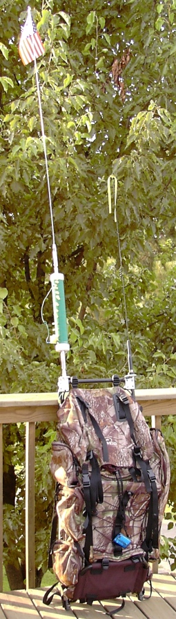
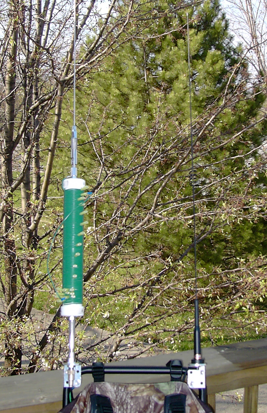
Pedestrian mobile HF/VHF backpack
Counterpoise Length
How long is the counterpoise? The overall length including the "pigtail" that is attached to the antenna bracket is the appropriate length for the frequency based on Bonnie KQ6XA's research. Here are some excerpts from the Counterpoise_Radial_Length file provided by the HFPack group.
Counterpoise wire touching Earth
The problem of predicting or computing the length of a resonant wire gets more complex when using dragging counterpoises and very low radials or radial wires laying partly on the ground. Because of proximity to the earth surface, the wire needs to be shorter. Earth (soil) conductivity affects the resonance, so different soil types may require different length counterpoises. Generally, the more conductive the soil, the shorter the counterpoise.
Pedestrian dragging counterpoise length With broadly tunable whips (such as MP-1, mobile whips, etc)
I've found empirically that a pedestrian dragging counterpoise wire can be about 10% to 25% shorter than the standard quarterwave formula predicts, and the whip will usually tune to a fairly good 50ohm match. Insulated wire with low ohmic resistance should be used. For best dragging quality, Teflon or slick PVC-jacketed or oil-resitant multistrand wire is best. For safety while walking with a dragging counterpoise, some sort of slip-connector or an alligator clip should be used so that the connection will break apart if the wire is caught by a rock or vegetation.
KQ6XA's dragging counterpoise length by band
  |BAND| FEET |
  |----|------|
  |10m | 7.4ft|
  |12m | 8.0ft|
  |15m | 9.9ft|
  |17m |11.0ft|
  |20m |14.0ft|
  |30m |18.5ft|
  |40m |26.3ft|
  |60m |34.3ft|
  |75m |45.4ft|
  |80m |49.3ft|
Pictures
- Back View Antennas
- Back View Full
- Front Full
- Front View Near Full
- Mounts, Pack and Counterpoise
- Quick Detach Counterpoise
- Coil Base
- Coil Top
- Coil Fine Tuning Section
- Coil On Grid
- Zip file with pics
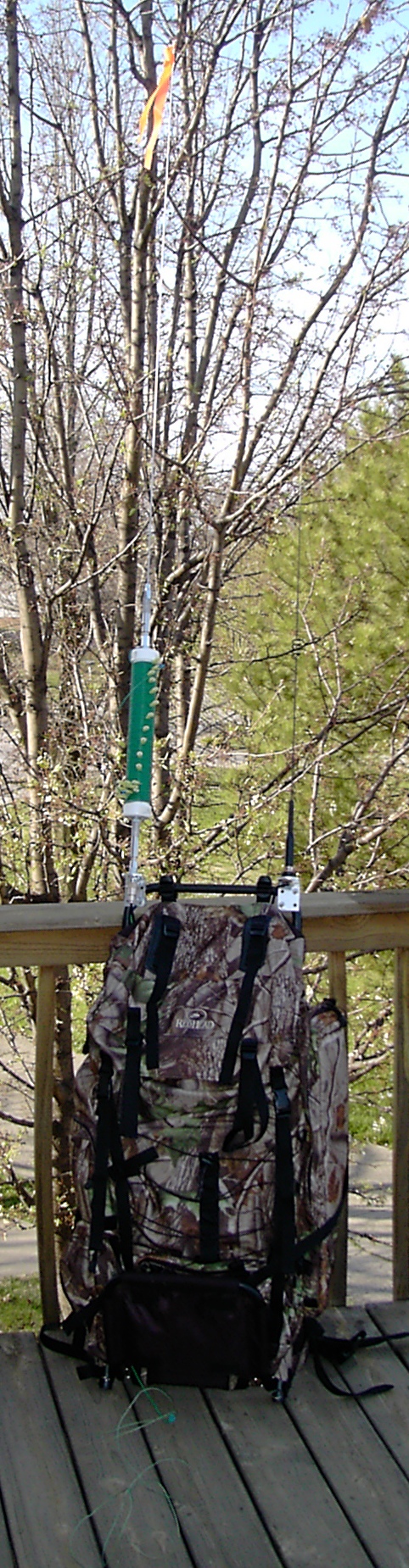
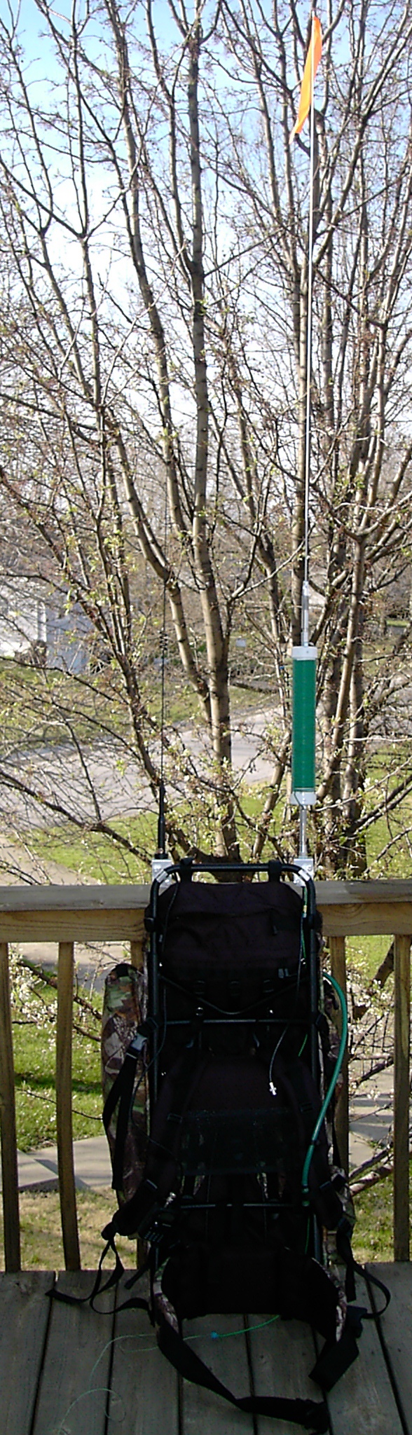
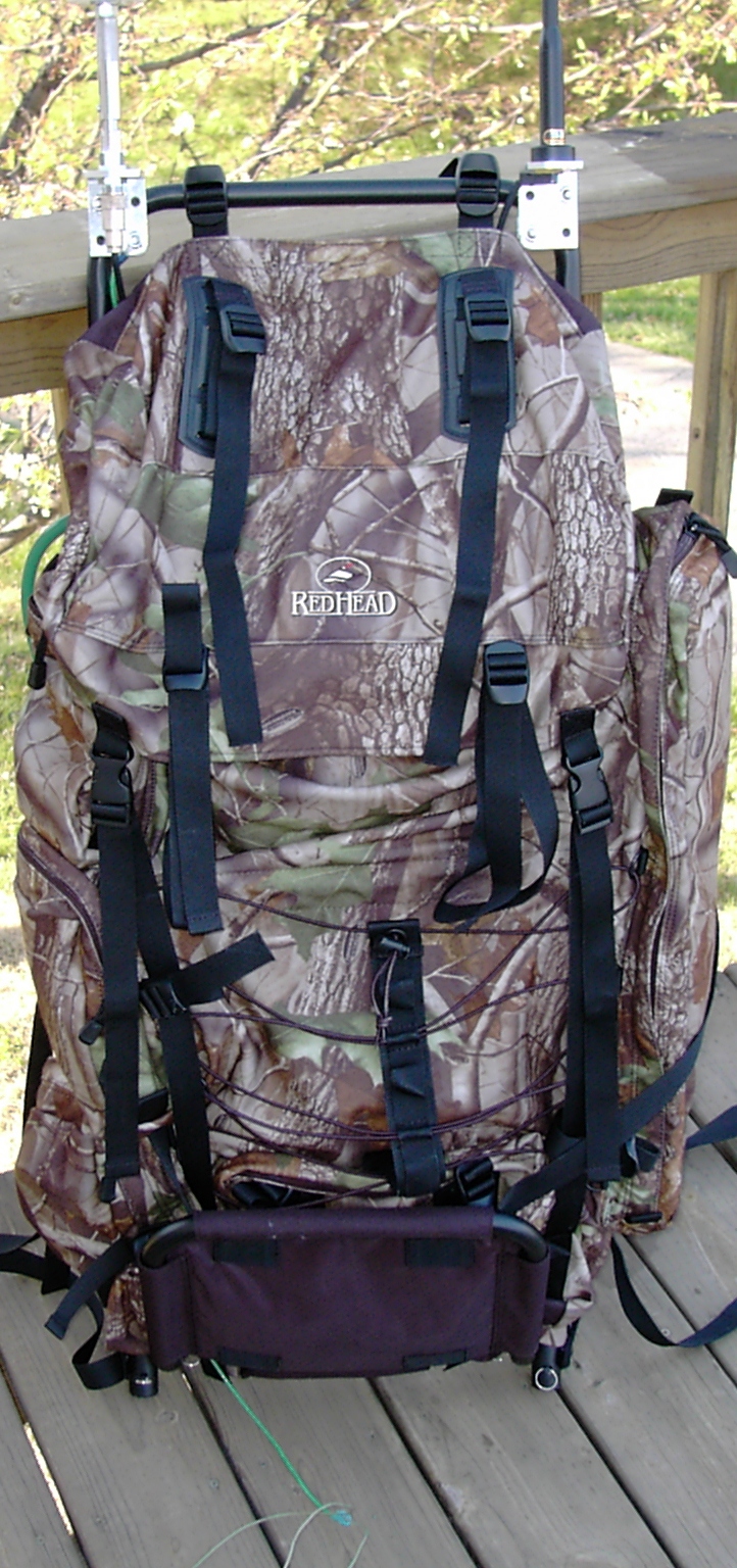
Backpack
I am using a bass pro big country pack. I picked this backpack for it's external frame, hydration pack and because it fit me! The frame and padding are set up really nice. They do a really good job of letting air circulate around. I was really surprised when I felt a breeze come across my back while wearing it.
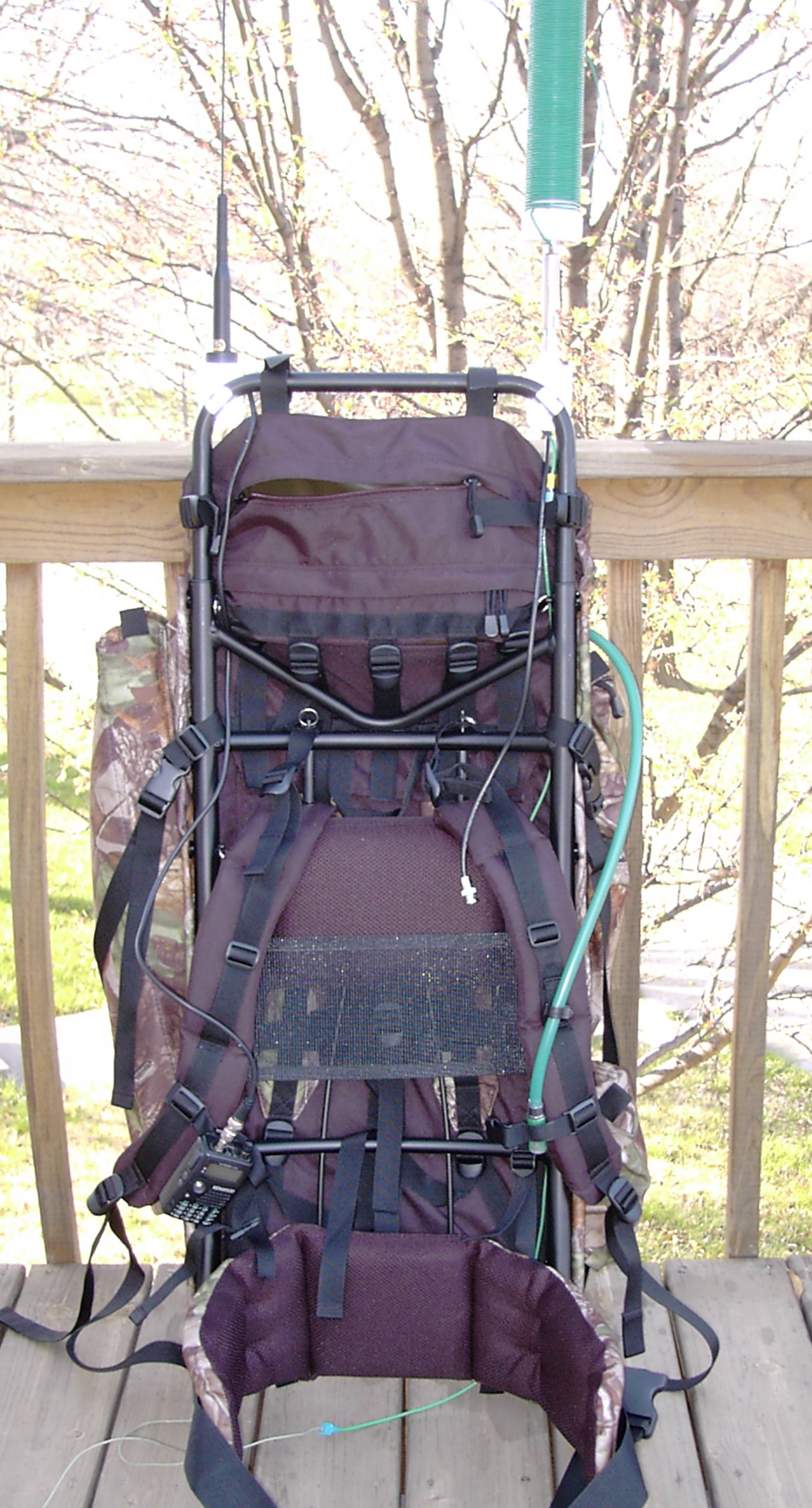
Antenna Mounts
I found some great brackets at a truck stop for mounting antennas. They are Barjan 300-306, "GM Models" prior to 1990 Mirror Mount. I did grind down the part of the bracket near to the pack.
One mount is configured with NMO so I have a lot of versatility with it. Using adapters can go to UHF or BNC F. Coax is terminated with BNC.
The other mount is standard 3/8-24 with a quick-detach stud. Connected a detachable counterpoise wire to one of the nuts on the mount.
VHF/UHF Station
I use a Kenwood TH-F6a mated with a Comet SBB-5 dual band antenna. The rig was an easy choice. The main factors were simultaneous dual VFO's, all-MODE recieve and excellent battery life. I can keep one VFO on a local repeater or simplex frequency. The other VFO can be monitoring 18.157.5 USB. So, then I don't drain the HF rig's battery in RX.
The antenna was a tough choice. In the end I went with a Comet SBB-5 because I like the black color with the pack, the height is just right, flexibility is good and I had one on hand. Why do I care about height for this antenna? As you wear the pack it is on the right side. I did this because typically a brush/trees that hang over the trail are lower on the outside. I'm going to see how this works out, but I will be very tempted to get one of the new Comet EX-510B NMO 6/2/440 antennas. It doesn't take much additional antenna on the F6a to really bring up the receive on HF.
HF Station
The Yaesu FT-817 is the rig that I use on the HF/50 side of the house. I use the homebrew vertical for the antenna.
- Use the whip only for 6/2M operation ~55 inches.
- Whip w/coil for 10m, 12m, 15m, 17m, 20m, 30m & 40M.
- With the 9ft whip, 80M
- With the 6 Meter whip and all of the coil bypassed the antenna is resonate in 10M band.
- With all coil in good to 4.2Mhz.
- With 9ft whip, good below 80M.
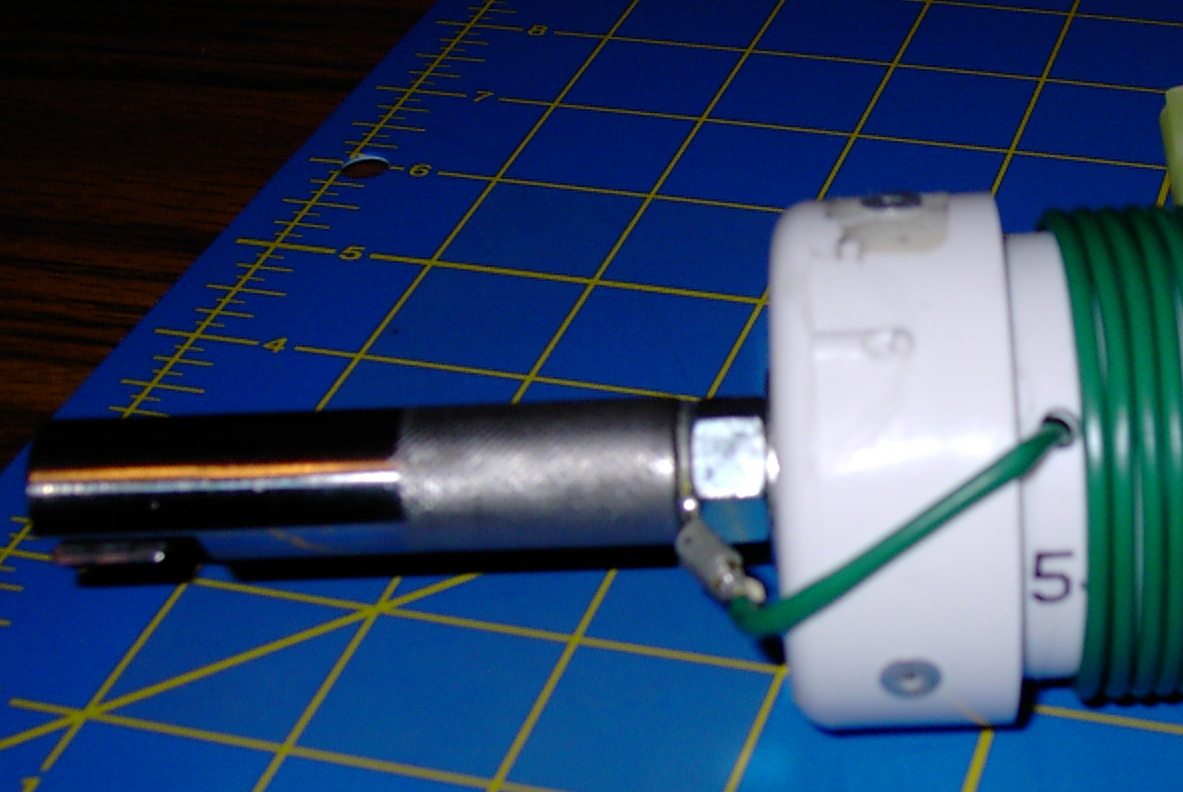
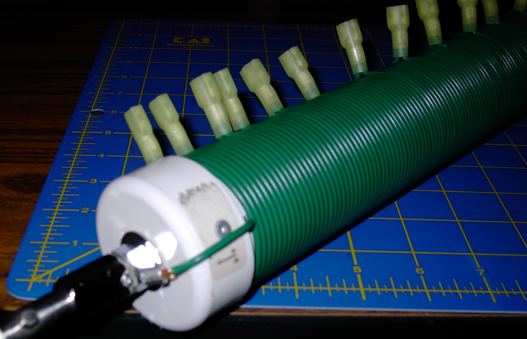
Antenna Construction
- I used 1 1/2" PVC for the coil form. Female Spade QD's for the taps.
- 16 gauge wire
- didn't calculate taps, evenly spaced at 10 turns.
- Bottom of coil has 10 turns that are tapped at every turn, use this as "fine tuning" section.
- Below fine tuning section is 3 turns.
- The coil itself is right at 12". This means that there is a little bit of empty space after the coil then the caps.
- Use vertical drill press to make holes for 3/8-24 TPI bolts in the flat end caps. Use lock washer and washer on inside of cap.
- End caps were glued on. Then riveted. PVC is a soft material so it is not unusual for the rivets to want to pull through.
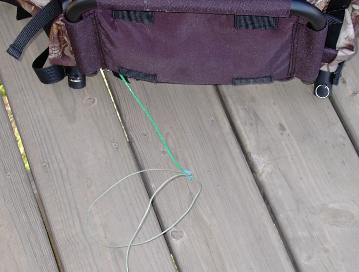
Counterpoise
I have a length of 14 gauge wire that has ring connector on one end and a female spade connector on the other. The ring connector is attached to the antenna bracket. The wire is routed down around the outside of the pack to where it terminates in the female spade connector. I then attach a counterpoise wire that has a male spade connector on the end. With this arrangement if the counterpoise gets hung up on something, it disconnects. Otherwise, the wire could pull on you causing you to lose your balance and fall. Not a good thing.
Now, the question becomes where to put the quick disconnect? Because of the way I have my wire routed I opted to put it a couple feet away from the bracket, past the end of the pack. My thought is to put the quick disconnect far enough out that you can easily reach back, grab the wire, pull the connector around in front of you and plug the dragging part back in. Saves you from having to take the pack off or from practicing to be a contortionist.
Also, take a piece of flagging tape and tie it to the part of the dragging counterpoise that is by the quick disconnect. Now when it comes unplugged you'll be able to quickly spot it. Optionally, use a brightly colored wire. But be prepared to have LOTS of people tell you, "you're dragging a wire."
Identification and Patriotism
I've also added a yellow ribbon (HFPack identification) to the VHF/UHF antenna. The yellow ribbon is also a traditional indicator of support for our troops. Thin, ribbed cloth type, melted the ends to keep from fraying.
On my HF antenna I added a US flag to the top. I used a flag that came on a round tube. Cut the top off the tube and again below the flag. Secured to the whip by putting zip-ties in place above and below the flag. HINT: wrap the zip tie twice and through itself to really snug it up! Now the flag waves freely when /PM.
Safety
When in an urban environment the ribbon and flag also serve as added visual attention getters. Especially handy when you're in hilly terrain. I sometimes find myself out during the twilight hours. For those times I have an LED flasher on the back of the pack. I also keep an LED flashlight in one of the pack pockets. Plan your route, follow your route, and make sure someone knows you're route and expected times. Pretty much your standard hiking/backpacking safety rules apply.
Be safe and have fun! 73 -- de Bryan, K0EMT
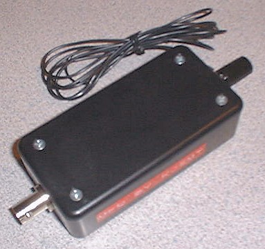
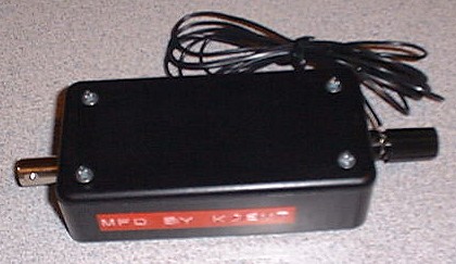
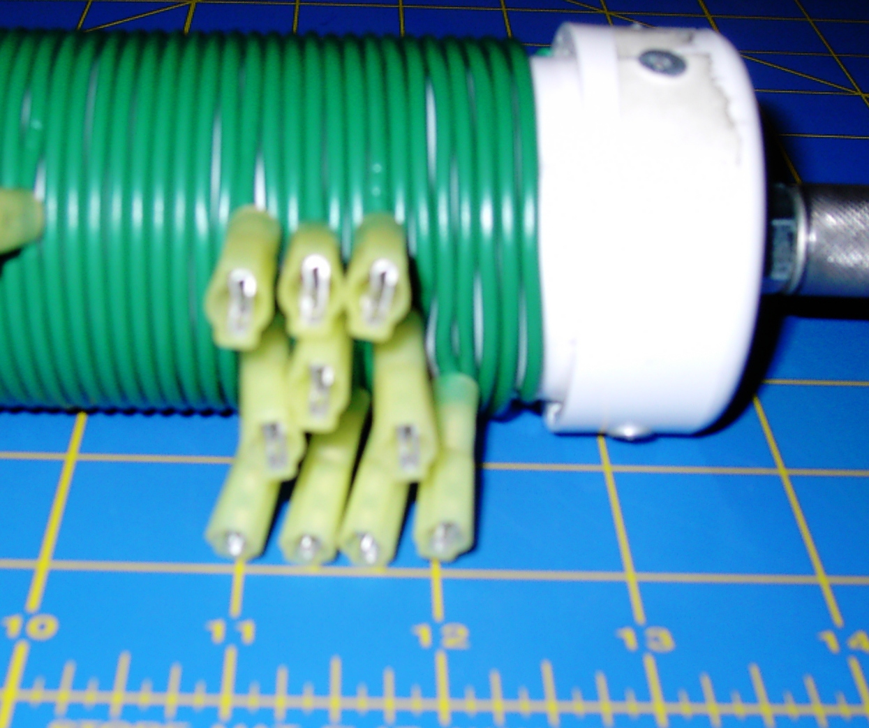
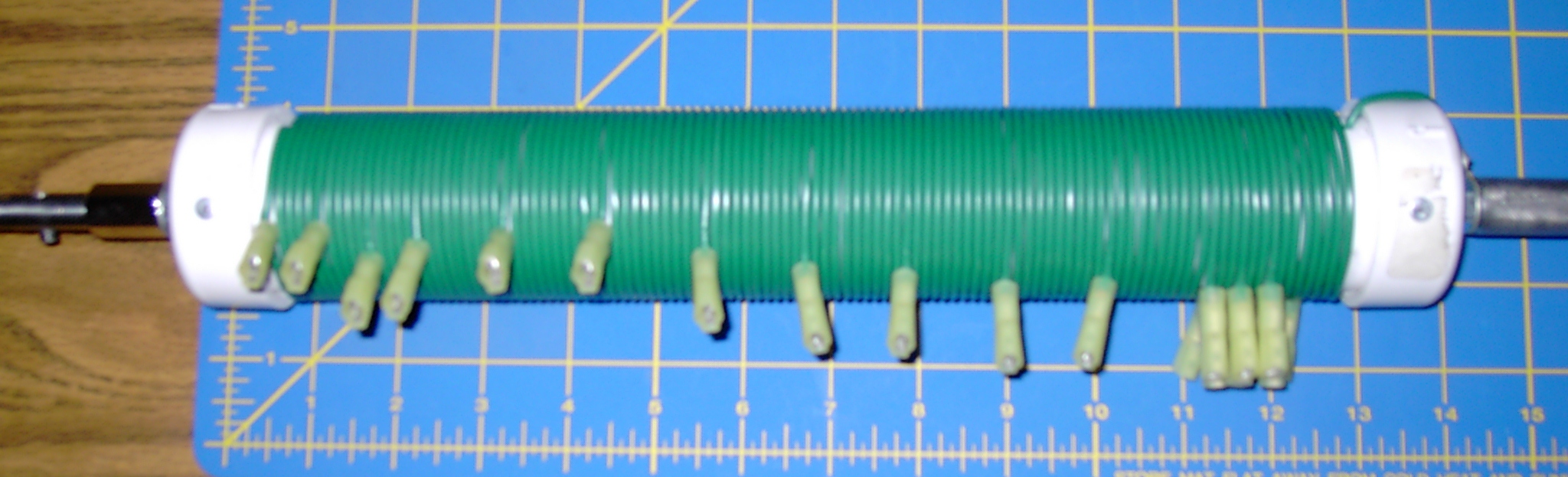
QRP Lowfer
The lowfer "kit" - a bit fuzzy SRI!
Close Up - very sharp!
Numerous people on several yahoogroups, of which I am a member,
have commented about portable HF antennas being a compromise in
performance versus convenience. I believe this antenna slams down
the scale on the side of convenience for operating 160M and 80M portable.
Materials
- Right Angle BNC Connector
- Radio Shack #271-133 - 50Ohm 10W Resistor
Construction
- Solder one wire of the resistor to the ground side of the BNC
Check for clearance with Plastic boot first! - Solder a jumper wire between the other wire and the center conductor of the BNC
- Replace plastic boot and Vinyl tape boot and exposed wire.
- Evaluate on antenna analyzer
- Have fun!
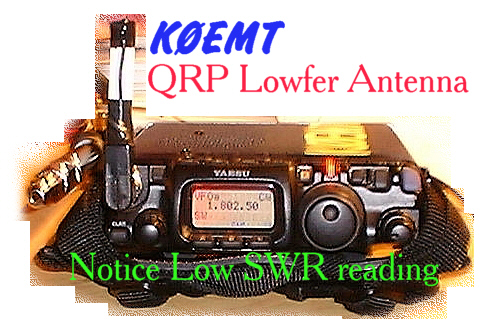
The analyzer showed low SWR on 160M and 80M. My FT-817 agrees.
40M and 30M show a bit higher SWR on the analyzer.
The 817 shows 3 and 4 bars respectively.
I was testing with 2.5W out CW.
Rigid Dipoles
I have been playing with PVC and Aluminum Tubing for building rigid dipoles.Most have been built for 10M, 6M and 2M. With the idea of portable operation.
There is a picture of a center "T" with BNC from one of these smaller antennas.
There are also a number of pictures of a 20M dipole here.
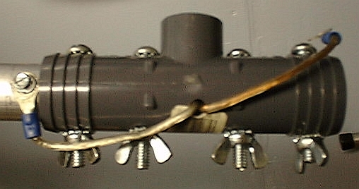
For this antenna, a coax "pig-tail" was connected to the interior bolts on the center T.
You will note the larger hole. This is so that a metal nut can tighten the assembly at this point
while providing a good physical and electrical connection to the antenna.
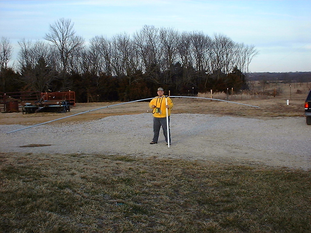
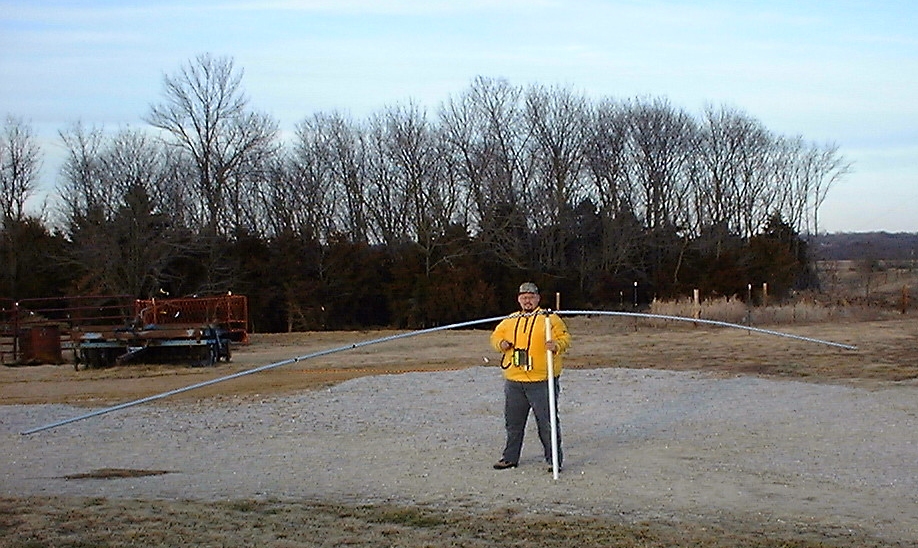
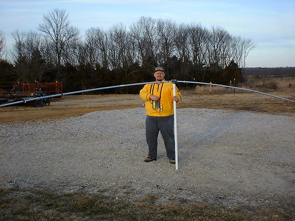
It is full-size, no loading. The antenna is in operation at the QTH of KB0HNR.
It is a top his 45ft tower.
Much to my surprise it has weathered severe storms with winds in excess of 60mph.
I hope that these pictures will help you in your construction projects.
Smaller rigid dipole
| K0EMT with 20M Rigid Dipole | 20M Rigid Dipole details |
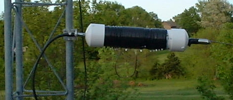
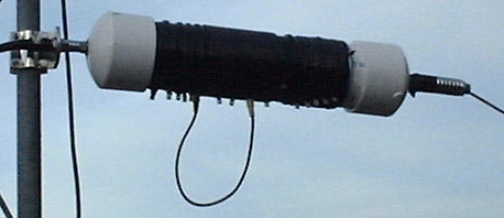
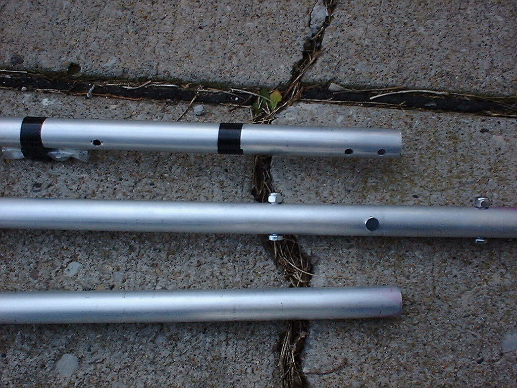
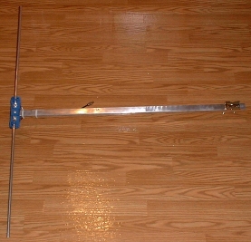
Side Mount VHF/UHF Antenna
|
This antenna is designed to be mounted off the side of a tower. The idea is to run the arm through the tower, bracketing to the far side of the tower. The middle of the arm should be zip tied to the tower. In the "laboratory" this antenna showed a VSWR of <= 2.0:1 from 136-153.1Mhz. With 1.1:1 at 144.2. This is good since the primary intent is to use it as a packet antenna. It also tested well for the entire 70cm band. |
 |
- Left over arm from scrapped CB antenna
- Left over element from converting Radio Shack FM antenna to 5el 2M beam
- Left over piece of dual-shield RG-58 coax
- Female BNC
- Mast mount bracket
- Polished arm, restoring appearance to near new
- Trimmed length of arm and installed mount bracket
- Drilled arm to accept a rivet through the element
- Riveted element to arm
- Installed ring connectors and Female BNC on coax
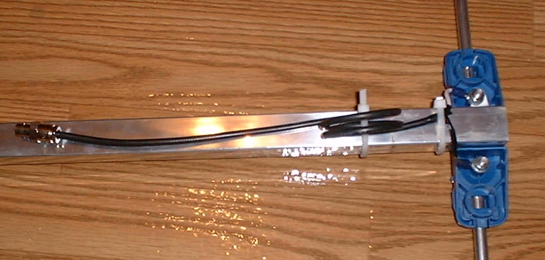
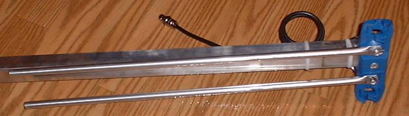
- Made several loops of coax to form balun
- Antenna to BNC
- Folded ready for transport
- Connections on the back side of the antenna
- Connection and Balun
- The Clamp
By the way, I will be going to black UV resistant ties before installing permanently.
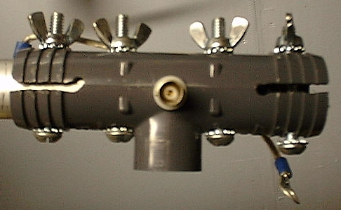
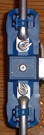
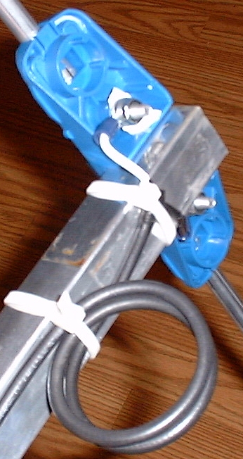
Trailer hitch mast mount
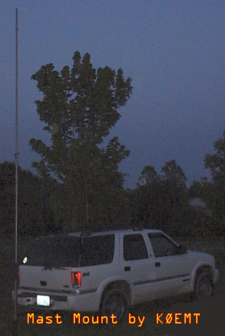
I designed this this mast mount because I wanted to be able to rapidly deploy a mast mounted antenna in a location that didn't have other supports available.
- Design Criteria:
- When not in use fit inside vehicle
- Be able to handle large to small diameter masts
- One person should be able to safely put up mast
- Should not require user to lift mast through top clamp
- Even if collar is loosened, it shouldn't slide down mast
- Should be a no-tools deployment
- Minimize moving parts
- Can open window portion of hatch while mount is in place
- The following was done to meet design goals:
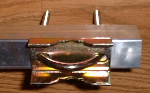
- Offset T-handled stainless bolts accommadate various sizes of masts. And permit a No-Tools securing of mast.
- "Tab" to keep collar in place
- To deploy this mast mount:
- Put the bottom collar on the mount first
- Secure the mount in the hitch
- Make sure the bolts are loose on the bottom collar
- Put your antenna on the mast, pulley for wire support, etc.
- Slide the top collar onto the mast
- Place the end of mast on top of the bottom collar
- Hold the smooth side of the collar in your hand, supporting the mast
- Support the mast with your other hand as well.
- Erect the mast keeping the bottom in the mast mount
- As you get near vertical the mast should drop to the ground inside the bottom collar
- Slide the top collar down into it's tab, making sure to orient it properly.
- Tighten down the top collar
- Tighten down the bottom collar
- Done!
After having practiced with this mast mount, I would likely have the bottom collar welded to the rest of the frame. Although that doesn't lend itself well to transport. So, it's a toss up.
John, AA0ZC built the mount for me. If you would like him to build one for you, contact him directly for an estimate.
VHF/HF Mobile Antenna by K0EMT
- Use the whip only for 6/2M operation
- Whip w/mast & coil for 10m, 12m, 15m, 17m, 20m, 30m & 40M
- 80M w/wire attached to QD mount
* End Cap & Mast
** Generation 1
   Bottom has a 3/8" x 24TPI bolt in a PVC end cap.
   Then a section of 1" aluminuum tubing.
   Overall length and coil weight of the Gen 1 have relegated
     it to a primarily portable HF vertical role.

** Generation 2
   Changed to a metal end cap, filling in extra space with PC-Metal Epoxy.
   Then a section of 1" aluminuum tubing.
   Mast shortened for mobile operation.

** Generation 3
   Copper tubing mast design.  Much nicer appearance.
   Field use demonstrated that the copper is too weak for extended use.

** Generation 4
   Fiberglass tube w/epoxy filled PVC cap

* Coil
  A smaller section of PVC slides inside of the mast.
  Coil is wound on the PVC.

** Generation 1
   Topped off with another bolt that has been pressed and epoxied into
   the PVC tube.   Then a whip tip adapter and a whip.
   Taps at various places, required tuner.
   Antenna ends up ~9'9" tall.  With full coil resonant at ~6.9Mhz.
   Bypassing coil it covers the entire 10M band < 1.8:1.

** Generation 2
   The bolt is simply put into the PVC end cap.
   Nut and whip tip adapter arrangement.
   Taps are located for resonant frequency, no tuner required.
   Coil shortened for better mobile operation, only goes to ~10Mhz now.

** Generation 3
   Nut and whip tip adapter configured with Quick Detach spade connectors.
   After 20M tap switch to smaller gauge wire, allows for 40M operation.

** Generation 4
   In progress, going to fiberglass coil form.
   Most likely will use PowerPole connectors instead of spade connectors.

* QSO's
First Contact, Generation 1
05 Feb 02 1035 CDT 28Mhz EA3XA 58 58 Jose - Barcelona Spain
			 w/ICOM IC-706 mk II @ 100 Watts

* 80M
Use a wire with Max Coil for 80M, works well for Section Traffic Net.
Better results on 80M can be obtained by using a 56" extender
below the coil.  (Stationary use only!)

* Costs
Al Tube ~$4 (~$12 for 8ft pc)
PVC Tube $1
Wire ~$4
Incidentals - Epoxy, Hardware, Ring Connectors, tape ~$2
3/8" Hardware - ~$7
Whip - ~$7
Total ~$25

10 Bands for about the price of 2 mobile monobanders.

* To Be Done
** Document
Where tapped, how chose where to tap.
How tapped, 14Gauge wire
length of each section
|
|
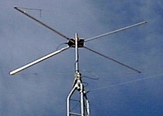
X-Beam Antenna
VHF/UHF X-Beam Construction Notes (and HF see update below) -- k0emt
I sat down and drew out what I did and thought I'd pass on what I did/found out. The design is from The 1993 ARRL handbook that was given to me by wd0hbx. The x-beam was originally intended as an HF mono-band beam. I used the formulas to build it for 6m. It also happens to work out really well for 2m & 70cm use as well.
The text says that this antenna design will typically have a 6-8dB gain and a forward to back ratio of 20dB. The handbook also states that this design should perform as well as or better than a similar yagi.
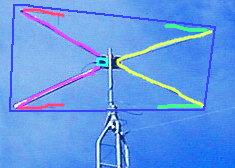
Notes:
(That will make more sense when you look at a
picture.)
There are tails on all four arms.
I didn't
have my arms exactly perpendicular.
I had the inside angle of
the directed element < 90 degrees.
I used square tubing on
the back and round on the front.
Tie the tails to the nylon
cord that is strung around the beam for support.
f       swr
(48.4 - 51.35) <= 2.2
50.110  2.2         420.000 1.3
50.125  2.2         426.000 1.6
52.525  2.5         430.750 1.6
                    435.000 1.1
144.000 1.1         436.300 1.6
145.050 1.2         442.000 2.0
146.000 1.3         444.000 1.6
146.400 1.4         445.000 1.1
146.520 1.4         446.000 1.5
148.000 1.2
|
 |
||||||||||||||||||
|
 |
On air testing has shown that it is indeed directional. Had S-8 noise on discone, switched to beam, now S-3. Conversely, when testing on 6M with a horizontally polarized "local" station kb0qhz, noted an improvement of 5 S-units when using beam. (cross polarization could come in to play though -- the discone is vertical.)
When testing with kb0hnr mobile in Jefferson City, MO I was able to copy him at times S5-9 when the discone couldn't even hear him. A similar gain was noted when hearing DX when cross-polarization shouldn't be an issue.
Noted, that when I changed the direction it is pointed wasn't able to bring up certain local 2M FM repeaters.
Hooked up an ICOM 706mkII, using 20w on 2M SSB made a contact with K9IMX (Lake of the Ozarks), he reported me 57. He regulary works n9wyx, another "serious" 2M ssb station within ~1/2 mile of my QTH and he said he was impressed with my signal.
As a side effect, it seems like the discone is peforming better now than before. The discone is mounted off the top of a 20' mast. The beam is approximately one foot under it. Maybe, it's benefitting from some sort of ground plane effect?
Overall, I'm fairly happy with this beam. I have the feeling I will be building another one this year. I'll use better materials and be more exacting on the next go around.
If anyone decides to build one, please let me know. I'd be glad to help any way
that I can and to stick it on the analyzer when you've finished construction.
2001 Jan 23 *******
kb0hnr was over recently. We had the antenna hooked up to my Kenwood TS-570S. The 570's tuner matched the rig to the antenna on 20 and 40 meters. We had a 59 contact into MA on 20m and were able to check into the 3905 net on 40 meters.
Not bad for a VHF/UHF antenna!
2001 May 31 ******
I now think that the reason the antenna was working on the HF bands was because it was so close to ground that there were some very strange interactions going on. The antenna was on a ground mounted 5ft Rohn tripod, with a 5ft Radio Shack Mast, Rotor & 4ft PVC mast attaching to the antenna. 2M and 440 were exhibiting good SWR but I was having a heck of a time with 6M. 6M would however tune.
Presently, I have moved the antenna a top a ~25ft Rohn 25G tower. As currently configured I have a 1.1swr for 144.2 and a 1.8swr for 432.1. 50.125 is currently showing a swr of 8.3, Rs=8 and Xs=17. Just this last weekend I added a 10' section to the tower increasing it to 25ft. I believe before I had done this that my swr was < 2.0 on 6M and on 2M,440 it was >1.5 but <3.0. I am coming to the conclusion that this antenna is very sensitive to it's height above ground.
For now, I plan to leave it as is, (I don't climb), and use the internal tuner of the TS-570S to make up the difference. Which it does just fine. By summers end I hope to add another two sections to the tower and a hazer. At that point in time I will try to adjust the antenna or make a matching circuit.
As an aside, the 570 will now tune the beam for 10M.
2001 October 09 ******
Beam is now at ~50ft. It is performing well.
Frequency and corresponding SWR as measured with MFJ antenna analyzer.
| Freq | SWR |
| 21.450 | 2.6 |
| 21.3-- | 2.8 |
| 21.0-- | 3.3 |
| 18.168 | 2.7 |
| 18.068 | 2.6 |
| 14.350 | 1.8 |
| 14.225 | 1.9 |
| 14.150 | 1.9 |
| 14.025 | 1.8 |
| 10.15- | 1.5 |
| 10.1-- | 1.7 |
| 7.3-- | 5.5 |
| 7.225 | 6.2 |
| 7.150 | 6.8 |
| 7.0-- | 8.2 |
| 4.0-- | 8.4 |
| 3.85- | 9.5 |
| 3.75- | 10.5 |
| 3.5-- | 25.5 |
| Freq | SWR |
| 446.0-- | 2.0 |
| 432.1-- | 1.4 |
| 148.0-- | 2.5 |
| 147.0-- | 2.0 |
| 146.0-- | 1.6 |
| 145.0-- | 1.5 |
| 144.2-- | 1.3 |
| 54.0-- | 1.4 |
| 53.0-- | 1.6 |
| 52.525 | 2.2 |
| 51.0-- | 3.2 |
| 50.125 | 3.4 |
| 29.6-- | 3.7 |
| 28.885 | 4.6 |
| 28.5-- | 6.0 |
| 28.3-- | 6.6 |
| 28.0-- | 7.5 |
| 24.99- | 4.3 |
| 24.93- | 4.1 |
| 24.89- | 3.9 |
I could not get my Kenwood TS-570SG to force feed the X-Beam on 28.337.
It did match it on 29.6. The rig will also not make the match on 40 Meters.
Obviously it won't make the match on 80 or 160 either.
2003 April 03 ******
It is VERY important that the arms be of a significantly larger diameter than the tails. More info on specifics can be found at LB's (W4RNL) page below.
Here are some additional web resources for your perusal.73,
Bryan - k0emt