5 Watter Phase 3
About
This post is a continuation in the series documenting my build of the 5 Watter Organic VCXO Transceiver.
Build Notes
In Phase 3 we are installing the keyer and keying interface sections.
I would also suggest that you solder R33 in place before J5. R33 sits between J5 and the socket for U5.
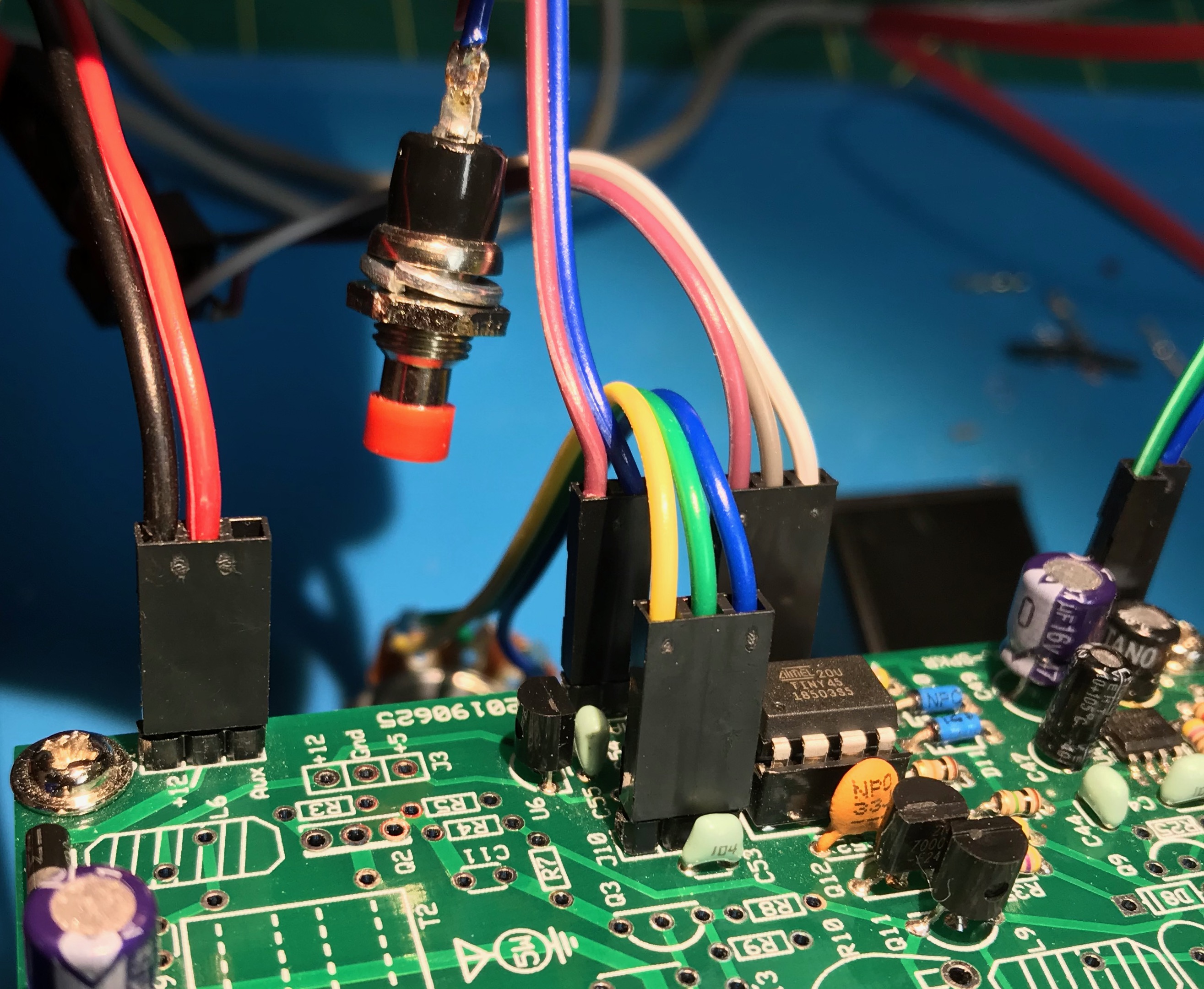
It is up to the builder to decide if they will hardwire directly to J4 and J5, or install Dupont headers. I opted to install Dupont headers. J4 is used for the command button. You’ll need this during the test phase. I wired the 2 pins next to the J4 designator to a momentary button. J5 is a 3 pin header. Ground is in the middle pin. Connect J5 to a “stereo” or TRS 3.5mm jack.
Refer to section 15 Connections, of the standard kitsandparts.com 5 watter building instructions for guidance on wiring up the jacks and pots.
During the testing of Phase 3, I discovered, that an “optional” 10K linear pot will be needed for the Morse Code speed control.
Cut the wire bundles that come with the mounting hardware in half. You’ll wire these to your connectors. You’re still going to need more wire for the speed pot and the DC jack. I found that having the proper crimp tool made working with the dupont connectors much easier. I ordered one of these Dupont crimping tool kits. The kit also contained extra wire which I’ve used right away.
The crimper is listed on My Workbench Page along with the other tools on my workbench.
Cases
I have started researching cases. This is the top enclosure contender at the moment. But I haven’t come to any decision yet.
Frequency Display
The tech group I am a part of is leaning towards adding a QRP Guys Digital Dial to our project.
K7QO Videos
We are following the K7QO guide that is on the kitsandparts.com kit page along with the kit documentation.
However, I discovered that in July Chuck did an independent video series building a 17m version. I created a K7QO 5 Watter playlist on YouTube.