T-Match Tuner

The Kit
This manual T-match tuner kit came to me via Amazon. It is also available via eBay and other online stores.
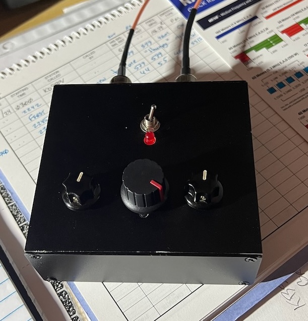
You build this kit into the bottom of the enclosure that is provided. I opted to build it into a 40 x 100 x 110mm aluminum enclosure. Around the machine bolt areas coating was removed to ensure the entire case is bonded together. During assembly, I bolted the main front panel and back panel together.
Don’t trust the sticker guides in the kit. Figuring out how to align them can be tricky with the default case internal structure. Size and locations may not match the hardware. A big gotcha can be the screws that hold on the polyvaricons (printed holes too big).
The board does not have through hole plating.
There is one capacitor that is provided for the N7VE tuning circuit. Make sure to check its value. Mine was out of spec by 50%! I replaced it from parts on hand.
The circuit diagram for the N7VE transformer is correct. However, the board is incorrectly labeled. 2T on primary, 5T on secondary.
Check that the provided enamel coated wire is of the correct size 22 AWG.
The knobs and hardware for the polyvaricons are awful. Plan on doing something different. Again, I pulled from parts on hand for shaft exentions and knobs.
Inductor taps
The 4S QRP T-match kit instructions tell you to do taps with the following number of turns: 1,1,1, 2,2,2, 2,2,2, 2,2,2.
Default instructions see the circuit diagram in the marcel wiki page give a sequence of turns starting 10,2,3,2,…
The correct way is to flip the order: 1,2,2,2,4,2,3,3,2,3,2,10
Why? Otherwise, your first turn is 10 turns. This is way too much.
What’s the benefit of this sequence. Fine tuning at the start for when you are using an antenna like a dipole or end fed half wave. Bigger jumps to get you into the 40m band when using an end fed random wire. And a really big jump at the end to help get you to 160m.
Build tips
Besides removing case coating from where it goes together, I also remove it where the BNCs were installed. There was good continuity between the BNC shield/ground side. However, for clarity I went ahead and connected the ground tabs together.
The switch and inductor:
- Ground side wire (grey) is connected to the center of the switch before connecting the toroid.
- Pre-tin the leads on the switch.
- Prep toroid taps by scraping insulation and melting away coating with solder.
- Check even length of leads on the toroid before soldering with switch
- This is one reason why 4S QRP kit approach may be better.
- Start by soldering the taps for 1, 12, and 11. This helps with holding the ends in place as well as keeping the 10 Turn section reigned in.
- Check clearance of toroid on the switch with the case before soldering.
The 4S QRP instructions tell you to set the polyvaricons to minimum. I didn’t do that.
Using the T-Match
The procedure:
- Tune to the desired frequency.
- Start with inductor at minimum, transceiver cap and antenna cap at mid position.
- Adjust inductor for maximum noise.
- Start with antenna side cap adjusting for maximum noise, then transceiver side.
- Flip the Tune/Transmit switch to Tune.
- Key the transceiver and adjust capacitors to the dimmest LED showing possible.
- DO NOT switch the inductor setting while transmitting.
- Stop transmitting. If you were not able to get a good match try reducing or increasing inductance and repeat the tuning procedure.
- Once you are satisfied, return the Tune/Transmit switch to Transmit.
My antenna is 9:1 unun, ~58’ end fed random wire, with an elevated radial that is ~17’ long to a 20m trap, then another 18'.
With this tuner and my antenna configuration I was able to get matches on all bands 10m-160m.
See the information on multiple ways to tune.
Final thoughts
I’m tempted to build one of these again. What would I do differently? I’d probably use the internals from a 4S QRP kit. The 12 position switch is much nicer mechanically to work with. I like the idea of a red LED diminishing as a green LED brightens for tuning. The shaft extensions for the polyvaricons and the accompanying knobs in the 4S kit are much better.
I do like the case and arrangement I used. I would need to construct something to implement the 2 color tune indicator.
Maybe, just build the 4S QRP kit, use the alternate number of turns and case mounted BNCs.